Quantcast
Channel: GameDev.net
Viewing all 17063 articles
Browse latest View live

Real-Time Cartoon Rendering with Direct-X 8.0 Hardware

$
0
0

Introduction
In an era of increasingly realistic game graphics, buzzwords like bump-mapping and per-pixel lighting take all the glory. The programmable hardware in today's consumer graphics cards does make these highly-realistic techniques available in real-time, but this same hardware makes stylized rendering available as well. Non-photorealistic rendering (NPR) is a branch of 3D graphics that has yet to be fully tapped for game use. With the advent of programmable shaders, a whole range of NPR styles are available that previously existed only in the pre-rendered domain.

This article focuses on using programmable hardware for a popular NPR technique: creating cartoon-like graphics from 3D models. Games are released every year that are based on cartoons but fail to convey the same look and feel as their subject matter. This work attempts to make cartoon-style graphics available to 3D game developers. It culminates in a powerful, fast cartoon renderer that will run on any Direct-X 8.0 compatible hardware.

We'll start by taking a quick look at our selected hardware, continue with a brief definition of cartoon rendering, describe the implementation details of our renderer, and finish with some benchmarks and ideas for the future. As you will see, our renderer is accessible: It runs on ATI and nVidia hardware and even the X-Box console. It is flexible: we can change the thickness, color, and style of our ink lines. We can modify shading styles by altering a single texture. It is fast: it runs at game-acceptable frame rates for scenes in excess of 40,000 polygons. Best of all, the frames generated by our renderer look great!


Limitations of our Hardware
Since the goal of this article is to create a DirectX 8.0 compatible cartoon renderer, there are certain things regarding our selected hardware that we should be aware of:

Vertex Shaders: We are limited to Vertex Shader language version 1.1 (VS 1.1) which means the 2.0 control instructions (if, call, etc.) will not be available to us. We are also limited in the number of registers and total instructions we can use, although all of the vertex programs in this article stay well under these limits.

Pixel Shaders: The first incarnation of the pixel shader language, PS 1.1, is a far-cry from what is available on more modern pixel shader hardware. The useful instructions that were added in language versions 1.2, 1.3, 1.4 and 2.0 will not be available. We are also limited to eight instructions per pixel program (sixteen if we are good at co-issuing instructions to the RGB and alpha pipelines).

Texture stages: We have only four texture stages, which is somewhat unfortunate, as the outlining technique we use would be more accurate with five. On the other hand, the 5th stage wouldn't be all that useful without a higher pixel shader instruction limit, so the absence of the additional stage is somewhat moot.

Rendering passes: Ideally, the entire scene would be rendered in one pass, but without the multiple render target support that exists on more modern hardware, our renderer is limited to a two-pass approach.


What Is Cartoon Rendering?
Cartoon rendering (sometimes referred to as cel-shading) has two major constituents: painting and inking. In the traditional sense, painting is filling a cartoon object with areas of color. A simple cartoon will use solid colors for different objects (flat-shading), but more complex cartoons use two or even three colors for each material. This is often called stepped-shading because the color "steps" dramatically from the shadow color to the highlight color. The stepped-shading effect looks quite different from realistic rendering techniques as there isn't a smooth gradient between the shadowed and highlighted areas of an object.

Inking mimics a traditional cartoonist's use of black ink to create a stylized world. In a cel-shaded scene, each object needs an "ink" line to separate it from other objects. It also needs lines to emphasize its features, to show sharp edges, and to separate any areas of differing color. In the examination of our renderer, we will look at the algorithms and implementations for painting and inking separately, as it represents a logical division of concepts.


The Evolution of a Cartoon Renderer
The cartoon renderer discussed in this article has been through many incarnations. A great deal of research and experimentation went into developing the current implementation of both the painting and inking components of the renderer. While the details of the different methods I have tested are beyond the scope of this article, more information about these methods accompanies the sample program and source code available from here. With that brief caveat, let's get our hands dirty with the renderer itself.


Painting
The first part of our cartoon renderer is the painter. As a minimum, a painter needs to support rendering an object with solid colors. A more advanced painter will generate stepped shadows and highlights using light direction, vary this shading with brightness, and even support multiple light sources.

Displaying objects with solid colors is rather trivial, but some research has been done into different stepped shading techniques. According to Claes [1], it is possible to choose a constant color (either highlight or shadow) for each polygon, but better results occur if some polygons are subdivided into two shades using linear interpolation. In order to use programmable hardware to achieve a similar effect, it is necessary to use the light direction vector and vertex normal to to sample a specialized shading texture. This is similar to the algorithm used by Lake [2].

The simplest hardware implementation of a painting algorithm that supports stepped shading uses a one-dimensional texture. A vertex program takes the direction of a single light and calculates the dot-product between the light and the vertex normal. A value of one means that the two vectors point in exactly the same direction, but as the angle between the two vectors increases, the value decreases. We can clamp the negative values to zero and use this result as a texture coordinate. A coordinate of 1.0 represents normals that are facing the light and should be bright, and a coordinate of 0.0 will represent normals that are facing away from the light and should be dark.

Our painter improves on this basic algorithm in three ways. Firstly, we calculate the dot-product per-pixel instead of per-vertex. This smoothes jagged shadow lines that can appear on low-poly models. Secondly, we support two directional lights for each mesh. Thirdly, we scale the texture coordinates with the brightness of the light, allowing brighter lights to expand the highlighted areas or even use an extra highlight shade.

The relevant part of the vertex program for our painter is shown in listing 1. It puts the transformed vertex normal into the first set of texture coordinates and the angle of the two lights in the second and third sets of texture coordinates. The light vectors are scaled by the brightness of the light before they are passed to the vertex program. This has the effect of scaling the eventual dot-product between the light and normal vectors.

Listing 1

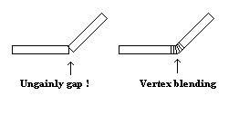
vs.1.1 ; painter vertex shader dcl_normal v3 ; transform normal dp3 r1.x, v3, c[INVERSE_WORLD_MATRIX] dp3 r1.y, v3, c[INVERSE_WORLD_MATRIX_1] dp3 r1.z, v3, c[INVERSE_WORLD_MATRIX_2] ; renormalize it dp3 r1.w, r1, r1 rsq r1.w, r1.w mul r1, r1, r1.w ; stick normal vector in first stage mov oT0, r1 ; stick first light position in second stage mov oT1, c[LIGHT_POSITION_A] ; stick second light position in third stage mov oT2, c[LIGHT_POSITION_B] Most of the work is done in the pixel program that is shown in listing 2. The first stage contains a normalizing cube-map. This is a specialized cube-map that converts interpolated normal values into renormalized values biased into the 0.0 to 1.0 range. This is more accurate than using the texcoord instruction to grab the coordinates directly, as linearly interpolated values can result in vectors with lengths less than one. Figure 1 shows how this occurs. The _bx2 instruction modifier is used to return the vectors into the proper range when they are needed for calculations.

Posted Image
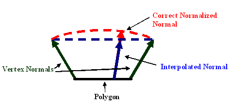
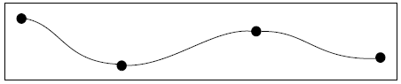
Figure 1: Because the vertex normal is passed to the pixel shader in texture coordinates, it is linearly interpolated per pixel. This interpolated value follows the blue line, leading to non-normalized values on smoothed polygons. The proper normal should follow the red line.

Listing 2

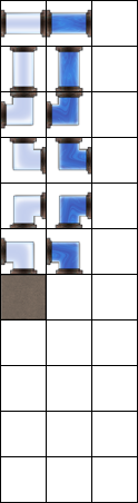
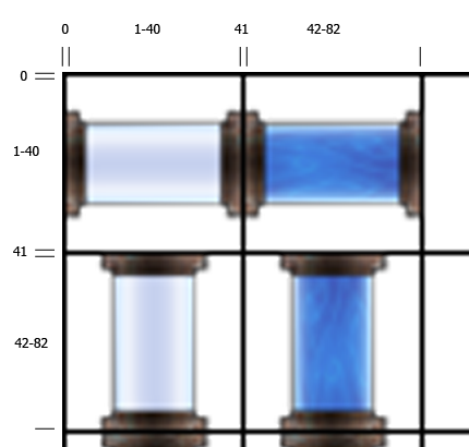
ps.1.1 ; painter pixel shader def c0, 0.0f, 0.0f, 0.0f, 0.75f ; light scale def c1, 0.0f, 0.0f, 0.0f, 1.0f ; black tex t0 ; grab the normalized normal ; normalizing cube map is in t0 texm3x2pad t1, t0_bx2 ; dot with light a for u value texm3x2tex t2, t0_bx2 ; dot with light b for v value ; 2d shade texture is in stage t2 tex t3 ; regular texture data mov r0, C_MATERIAL_DIFFUSE ; load constant color in cnd r0, r0.a, r0, t3 ; if alpha, use color ; else, use texture mul r1.rgb, r0, t2 ; modulate with shading mul r0.rgb, C_LIGHT_COLOR, c0.a ; scale down light value mul_x2 r0.rgb, r0, r1 ; modulate x2 with light color The texm3x2pad and texm3x2tex instructions are used to perform the dot-products between the light angles and the normal. The resulting two scalars are used as u and v coordinates to sample the shading texture which is placed in the third stage. As seen in figure 2, the shading texture has dark pixels at (u=0, v=0) and lightens in steps as the values increase to (u=1, v=1). The number of steps and their relative size is determined by the texture, so it is easy to create a completely different shading style by swapping in a new one.

Posted Image
Figure 2: The shading texture used by our painter. Shadow shades appear in the upper left corner and lighten toward the right and bottom of the texture.

Remember that the light angle is scaled by the brightness of the light, so a half-bright light will generate texture coordinates lower than 0.5. It is therefore possible to create a highlight shade that only shows up around bright lights. This scaling also makes it possible for one of the two lights that are illuminating the model to appear brighter than the other.

Our shading is modulated with either a constant color from the material or the sample from the fourth texture stage, which can contain a standard texture. We then modulate this color with a light color that is passed to the pixel program via a constant. We use a combined light color because applying one color to some pixels and a second color to other pixels creates a gradient that spoils the stepped shading. We also overbrighten the model color based on the light color. Modulating by 2 is too extreme, so we scale the light color by 0.75 before doubling it. This results in 1.5x modulation and gives very nice results.


Inking
The second portion of our cartoon renderer is the Inker. There are three different categories of lines that we want our inker to take care of. The first type is an outline that surrounds each model, distinguishing it from surrounding objects. The second type of line is drawn on sharp edges or creases in the model to accentuate its features. The third type of line is the characteristic line created by an artist. These lines could be used on a flat model, for example, or to emphasize a character's facial features that aren't distinct enough in geometry to generate an edge-line.

A great deal of investigation has been done into world-space line-generation techniques. Buchanan [3] recommended using an edge buffer to keep track of edge polygons. Raskar [4] developed methods of extending back-facing polygons to create outlines and edges. The researchers at nVidia [5] show how to use a vertex program to generate outlines on a model. Mitchell [6], was the first to suggest using modern hardware to create outlines by comparing pixels in image-space.

Despite the prevalence of world space techniques, edge-lines and and artist-lines almost always require the generation of new geometry and/or the maintenance of software information that doesn't translate well to programmable hardware. The vertex-shader outlining technique is reasonably effective for high-poly, smooth models, but its quality is simply unacceptable for low-poly and angular models. Programmable pixel shaders make image-space edge detection techniques possible at real-time frame rates. We are therefore going to use image-space techniques for our inker.

So, how do we use pixel programs for image filtering? It is first necessary to put the source image in all four texture stages. Then we create a vertex program that offsets the texture coordinates slightly. For example, we move the coordinates for the first stage up and to the left the equivalent of one pixel. We move the third stage down and to the right and similarly offset the second and forth stage down-left and up-right, respectively. Listing 3 shows the code for a simple vertex program that does this. The four texture stages allow a pixel program to sample four input pixels for each output pixel. It is possible to do sharpening, blurring, and even luminance edge detection in short pixel shader programs.

Listing 3

vs.1.1 ; texture coordinate offset vertex shader dcl_texcoord0 v1 mov a0.x, c[OFFSET_SET].x ; grab the proper offset ; c[OFFSET_SET].x is the number of the constant register ; that contains the first of four x and y offsets. add oT0, v1, c[a0.x + 0] add oT1, v1, c[a0.x + 1] add oT2, v1, c[a0.x + 2] add oT3, v1, c[a0.x + 3] The only disadvantage of the image-filter approach is that it is now necessary to render every object in the scene twice: once, into the back buffer to create the cartoon shading and, again, into a texture that can be placed in the four texture stages of the image-filter pixel program. More modern hardware can use multiple render targets to do this in one pass, but our selected hardware doesn't allow it. For now, we have to live with a 50% frame rate hit that will translate into lower poly in-game models than could otherwise be used.

Our inker generates a set of lines in a texture that is the same size as the back-buffer. This texture will be applied to a single quad and rendered over the top of our shaded scene. This doesn't really constitute a third rendering pass, because only two triangles are sent to the hardware. It can have an impact on frame rate, though, as it pushes the hardware's fill-rate, especially in high-resolution modes. Remember that our pixel program will have to run once for each pixel on the screen, so higher resolution means lower frame rate. Fortunately, the impact is fairly constant for each resolution, regardless of how many polygons are in the underlying scene.

To use an image-filter for ink line generation, we need to render a version of the scene that has information encoded into color values. The RGBA components represent the only data available to our pixel program, so we need to use them wisely. We will use the alpha component to store depth information that our image-filter will turn into outlines. The RGB values will be used for both the edge-lines and the artist-lines. Edge-lines need to be generated when neighboring pixels have vertex normals that face in drastically different directions, so we need to encode these normals as RGB colors. To do this we can use the same normalizing cube-map that we used for the Painter.

Our shader supports artist-lines via two different methods. It can use info stored in vertex colors or info stored in a texture. Unfortunately, we can only generate one set of RGB values for each pixel in the scene. Therefore each set of polygons can use either edge-lines, vertex color artist-lines, or texture artist-lines, but only one of the three. It is easiest to specify the type of line per-material, so each section of an object can use a different method.

Our pixel program will calculate the dot-product between neighboring pixels to determine if an edge-line is required. It is to our advantage to encode artist-lines as normalized vectors in order to use the same dot-product method. We don't want our artist-generated colors to interfere with the normal-generated colors, so we're going to use the set of RGB encoded normals that is facing away from the camera. Essentially, we're going to use four colors that represent normals that are not in view from the current camera location. The two artist-line algorithms do this in slightly different ways.

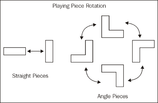
The first method for artist-lines uses vertex-color information. We pick four colors that represent normals that are equidistant from the x-y plane and from each other and paint polygons in the model with these colors. An example of four possible vectors and colors is shown in figure 3. These four colors should be enough to generate lines on even complex models if they are used wisely. Lines will appear in between polygons that we have painted with different colors. In the renderer, a vertex program converts the colors back into normals and rotates them so they point in the same direction as the eye-to-vertex vector. This generates normals that are always pointing away from the eye and therefore colors that won't interfere with our edge-line colors.

Posted Image
Figure 3: The figure shows four unit vectors that are separated from each other and a plane by approximately 45 degrees. The encoded RGB values for these vectors are included below the XYZ coordinates.

The second method uses four colors as well, but in this case we generate a dynamic 2x2 to contain them. The four normals are rotated to face the same direction as the eye-to-object vector, encoded, and placed in the texture in every frame. Because we rotate the vectors per-object, the results won't be quite as accurate as the per-vertex method. When we are close to large objects, some lines may disappear as the artist-line colors enter the same range as the edge-line colors. We sample the dynamic 2x2 texture using the pixel shader texreg2ar instruction. This instruction interprets the red and alpha values of a supplied texture as texture coordinates to sample a second texture. This essentially replaces four input colors from an artist-supplied texture with our four dynamic colors.

Our render texture now has the data needed to generate ink lines. Listing 4 shows the image-filter pixel program that does this. It compares opposite pixels, looking for differing colors and depth values. Ultimately, it depends on the one conditional instruction available in PS 1.1: cnd. This instruction will choose between two source colors and based on a single scalar. There are constant-supplied depth and edge thresholds that will specify the difference needed for RGB and alpha values to generate ink lines.

Listing 4

ps.1.1 ; inker pixel shader def c0, 0.0f, 0.0f, 0.0f, 0.9f ; threshold for normals def c1, 0.0f, 0.0f, 0.0f, 0.25f ; depth threshold def c2, 1.0f, 1.0f, 1.0f, 0.0f ; white and transparent def c3, 0.0f, 0.0f, 0.0f, -0.25f ; depth adjustment tex t0 tex t1 tex t2 tex t3 dp3 r0.rgb, t0_bx2, t2_bx2 ; dot the normals for opposite pixels +sub r0.a, t0.a, t2.a ; find depth differences dp3 r1.rgb, t1_bx2, t3_bx2 ; repeat for other set +sub r1.a, t1.a, t3.a mad t0.a, t0.a, c3.a, c0.a ; scale the normal threshold with depth ; uses first texture stage pixel sub_x4_sat r0.rgb, r0, t0.a ; subtract the normal threshold and clamp +mad r0.a, r0.a, r0.a, c1.a ; square the differences + add threshold sub_x4_sat r1.rgb, r1, t0.a ; repeat for other set +mad r1.a, r1.a, r1.a, c1.a mul_x4_sat r0.rgb, r0, r1 ; combine the clamped normal values +add r0.a, r0.a, r1.a ; combine the differences add r0.a, 1 - r0.b, r0.a ; combine depth and normal values cnd r0, r0.a, C_LINE_COLOR, c2 ; set pixel line color We also scale the edge threshold with the depth value of one of the pixels. This solves an annoying problem of smooth sections of the model turning into lines in the distance. You may need to modify the edge threshold and depth adjustment values. Optimal values depend on resolution, far plane distance, and the general look of different models in your game.

It is common for games to use partially-transparent textures for objects like fences and leaves, where modeling features in geometry would increase the polygon count drastically. This will work with our inker as long as we include alpha values when we render the object into the overlay texture. The best method for this is to use 1-bit alpha and turn on alpha-testing. Zero alpha pixels will be discarded and lines will be drawn around areas that remain visible.

Our inker also supports different line widths by changing the size of the render texture. A texture that is twice the size of the back buffer creates nice thin lines, assuming the hardware can support render surfaces that large. Smaller textures can create thicker lines, but these lines tend to look more pixilated as they thicken.

A better approach for thickening lines is to render the overlay lines into a second render texture instead of the back-buffer. This second texture is overlaid again with a "dilating" pixel program. This method is quite fast for low-resolution output, but can be limited by fill-rate in high-resolution modes. Listing 5 contains two pixel programs that use slightly different algorithms to "dilate" the original ink lines. The first pixel program thickens the lines by outputting an ink line pixel if any of the four sampled pixels are ink line pixels. The second pixel program creates smoothed lines by linearly interpolating between the line-color and transparent depending on how many ink line pixels are sampled.

Listing 5

ps.1.1 ; dilation pixel shader def c0, 0.0f, 0.0f, 0.0f, 0.25f ; for 1/4 multiplication def c1, 0.0f, 0.0f, 0.0f, -0.75f ; for subtracting def c2, 1.0f, 1.0f, 1.0f, 0.0f ; white and transparent tex t0 tex t1 tex t2 tex t3 mul r0.a, 1 - t0.a, c0.a ; sum 1/4 of inverse samples mad r0.a, 1 - t1.a, c0.a, r0.a ; alpha of lines are 1.0 alpha mad r0.a, 1 - t2.a, c0.a, r0.a mad r0.a, 1 - t3.a, c0.a, r0.a add_x4 r0.a, r0.a, c1.a ; subtract .75 and mul * 4 ; only transparent pixels will ; remain transparent cnd r0, r0.a, c2, C_LINE_COLOR ; conditionally choose between ; transparent and line color ps.1.1 ; smooth dilation pixel shader def c0, 0.0f, 0.0f, 0.0f, 0.5f ; smoothing threshold ; 0.25 = max smoothing ; 1.0 = no smoothing def c2, 1.0f, 1.0f, 1.0f, 0.0f ; white and transparent tex t0 tex t1 tex t2 tex t3 mul r0.a, t0.a, c0.a ; combine the four samples using mad r0.a, t1.a, c0.a, r0.a ; threshold and clamp mad r0.a, t2.a, c0.a, r0.a mad_sat r0.a, t3.a, c0.a, r0.a mov r1.rgb, C_LINE_COLOR ; create a zero alpha version + mov r1.a, c2 ; of line color lrp r0, r0.a, C_LINE_COLOR, r1 ; interpolate line color
Speed and Quality
Figure 4 shows a frame-rate comparison using a 64 megabyte Radeon 9000 mobile card. As you can see, the speed of the painter is highly-dependant on the number of triangles in the scene. In the worst case, its speed is 67% of the speed of rendering the same polygons normally. The initial rendering of the inker is similar in speed to painter, but there is a consistent speed loss for each quad that is overlaid on the screen. This loss is about 4 ms per frame at 800x600 and about 17 ms per frame at 1280x1024. The results from this card are completely acceptable at 800x600 with the shading, outlining, and dilation turned on, and the results are passable at 1280x1024.

800 x 600

40,000 poly model 26,000 poly model 1200 poly model Untextured Polygons 187 fps 232 640 Painter 137 173 555 Inker 91 104 150 Inker + Dilation 67 72 94 Painter + Inker 56 68 140 Painter + Inker + Dilation 46 53 89 1280 x 1024

40,000 poly model 26,000 poly model 1200 poly model Untextured Polygons 128 fps 134 250 Painter 87 91 220 Inker 35 36 43 Inker + Dilation 22 22 25 Painter + Inker 27 28 41 Painter + Inker + Dilation 19 19 24 Figure 4: The above results were obtained using a 64 megabyte Radeon 9000 Mobile graphics card in a laptop with a 3.06 GHz processor and 512 Megabytes of RAM

Figure 5 shows a couple of screenshots from the cartoon renderer we have developed. As you can see, the results are quite satisfactory. There are only two potential problems with the quality of our renderer. First, lines will occasionally disappear or reappear as we move around a model. This is due to new pixels coming into view and therefore new edges appearing that were not visible in the previous frame. Second, the shadow-boundaries generated by our painter can appear a bit fuzzy. It is a matter of preference as to whether these soft edges improve or worsen the look of the renderer.


Posted Image Posted Image Posted Image Posted Image Figure 5: Screenshots from the demo program illustrating the high-quality achieved by the Cartoon Renderer. As a whole, the results are far better than the results I have seen from other methods. In my opinion, the renderer is powerful enough to be used in a commercial game in its current incarnation, and any improvements that are made to it would simply be icing on the cake.


Future Refinements
While quite powerful in its own right, there is no doubt that further additions could be made to the cartoon renderer we have developed in this article. One possible modification would be to change our painter to use point lights instead of directional lights. To accomplish this it would be necessary to implement light-falloff and brightness calculations inside the vertex program. The light direction vector would need to be scaled inside the vertex program as well.

Another fascinating addition would be to create varied line-styles for the inker. This could be accomplished by rendering the lines onto something other than a simple quad. For example, one could use a 16x16 mesh of quads that could be perturbed according to some semi-random calculations in a vertex program. This could give a sketchy look to the lines, as they would move slightly each frame. Other interesting line-styles are made possible by replacing the "dilation" pixel program. We have only used this second pixel program to thicken the line, but one could also change look of the ink lines by offsetting individual pixels or changing their colors.


Conclusion
Our cartoon renderer gives us freedom in the look of our painting, even allowing us to use different highlighting depending on light brightness. It also has the flexibility to completely change highlighting schemes by switching out a single texture. It supports two, colored, per-pixel lights that can have varying brightness. Our outlining algorithm supports depth-based lines, automatic edge and crease lines, as well as artist-specified lines. All of these lines are rendered with a consistent style and can be drawn in varying widths and even smoothed.

This all adds up to possibly the most robust cartoon renderer developed to date, and it runs on all Direct-X 8.0 compatible hardware. It will even work on an X-Box! I would love to see the techniques described in this article implemented in a commercial game. We need to break the monotony of run-of-the-mill "realistic" graphics that are so prevalent in today's entertainment software. If anyone has questions regarding the cartoon renderer or any improvements that they wish to share, please contact me at vishvananda@yahoo.com.


For Further Information
Most of the papers referenced below can be found at the Citeseer website at http://citeseer.nj.nec.com. You can also find more information included with the demo program here.

[1] J. Claes, F. Di Fiore, G. Vansichem, F. Van Reeth. Fast 3D Cartoon Rendering with Improved Quality by Exploiting Graphics Hardware. 2001

[2] A. Lake, C. Marshall, M. Harris, M. Blackstein. Stylized Rendering Techniques for Scalable Real-Time 3D Animation. 2000.

[3] J. Buchanan, M. Sousa. The edge buffer: A data structure for easy silhouette rendering. 2000

[4] R. Raskar. Hardware Support for Non-Photorealistic Rendering. 2001.

[5] NVIDIA's Vertex Toon Shader http://developer.nvi...on_Shading.html

[6] J. Mitchell, C. Brennan, D. Card. Real-Time Image-Space Outlining for Non-Photorealistic Rendering. 2002. http://mirror.ati.co...ng_Mitchell.pdf


Getting DirectX 8.1 to Work with Dev-C++

$
0
0

Getting DirectX 8.1 to Work with Dev-C++ 4.9.8.1
by Sherman Chin

I have noticed that many people would like to know how to use DirectX with Dev-C++ because the beta version of Dev-C++ does not seem to work with DirectX very well until you do some tweaking and the official Dev-C++ site itself does not provide much help. So, I will write about how to get the free Dev-C++ compiler to work with DirectX 8.1 and thus, provide the user with a major tool that is needed to code state-of-the-art games . Now, even my game engine (www.Sherman3D.net/download/files/VFVer1.zip) is fully compilable in Dev-C++ 4.9.8.1.

Want to know how? Then follow these easy steps (they might look simple now but it took a lot of trial and error):

  1. Install Dev-C++
  2. Use the "Check for Updates/Packages" option in the Tools menu.
  3. Download the Direct9 package (which also includes DirectX 8.1)
  4. Select the "Project Options" item from the Project menu. Click on the Parameters tab.
  5. In the "Linker" section, click on "Add Library or Object" and add the necessary library files for DirectX. Here is what my list looks like:
    -lkernel32 -luser32 -lgdi32 -lwinspool -lcomdlg32 -ladvapi32 -lshell32 -lole32 -loleaut32 -luuid -lodbc32 -lodbccp32
    ../../../Dev-Cpp/lib/libdsound.a
    ../../../Dev-Cpp/lib/libdxguid.a
    ../../../Dev-Cpp/lib/libd3d8.a
    ../../../Dev-Cpp/lib/libd3dx8d.a
    ../../../Dev-Cpp/lib/libd3dxof.a
    ../../../Dev-Cpp/lib/libdplayx.a
    ../../../Dev-Cpp/lib/libwinmm.a
    ../../../Dev-Cpp/lib/libdxapi.a
    ../../../Dev-Cpp/lib/libwsock32.a
    ../../../Dev-Cpp/lib/libdinput8.a
    ../../../Dev-Cpp/lib/dinput.lib
    ../../../Dev-Cpp/lib/strmiids.lib
    

    As you can see, I am using Direct3D, DirectSound, DirectPlay, DirectInput and DirectShow. There are a few other necessary Windows libraries as well. I also added dinput.lib from the Microsoft DirectX 8.1 SDK (download it from Microsoft's site) because the one included with Dev-C++ (libdinput.a) seems to be missing some required data formats. The strmiids.lib, a DirectShow library for playing cutscenes, is not present in Dev-C++ so I added it from the DirectX 8.1 SDK as well.

  6. You are bound to run into compile time errors as the *.a DirectX library files that come with Dev-C++ have some typo errors in them. They are usually quite easy to fix though. Here is an example:
    Error message: something or other already defined in example.h
    Reason: #ifdef _EXAMPLE_
    Correction: #ifdef _EXAMPLE_H
    

    I can't really remember the exact typos as I corrected all of them without keeping the original files.

    In dxfile.h, delete the last line.
    In dmdls.h, change #ifndef MAKE_FOURCC to #ifndef MAKEFOURCC
    In dmdls.h, change WLOOP[1] to Wloop[1];
    In strmif.h, change #ifndef _WINGDI_ to #ifndef _WINGDI_H

  7. The biggest problem for me was getting DirectShow to work. First of all, comment out all the VMR stuff in strmif.h. I seem to get a GUID conflict if I don't. So just comment out lines 20551-20556, 28733-28759, 28759 till 28945. It is going to be a tedious process as there are many /**/ in between and you need to do a // for each line lest you miss out one of those #endif's like I originally did >_<.
  8. Another DirectShow problem is that you need to include atlbase.h to for automatic conversions from char to wchar but Dev-C++ doesn't come with atlbase.h. I did the filename conversion manually using a Win32 function. Replace wcscpy(wFileName, lpszMedia); (the function that is used by the DirectShow examples in the SDK) with
       MultiByteToWideChar(CP_ACP    ,     // code page
                           MB_PRECOMPOSED, // character-type options
                           lpszMedia,      // address of string to map
                           -1,             // number of characters in string
                           wFileName,      // address of wide-character buffer
                           MAX_PATH        // size of buffer);
    
  9. Dev-C++ doesn't seem to support the allocation of memory space with the "new" command using a variable for the size of memory to allocate. So, if you have something like this:

    m_Polygons = new sPolygon[m_NumPolygons]();

    Replace it with:

    (void*)m_Polygons = malloc(m_NumPolygons*sizeof(sPolygon));

  10. Dev-C++ uses the debug libraries of DirectX so please put d3dx8d.dll (which can be found in the DLL subdirectory of Dev-C++) in your program's directory when you distribute it.
  11. If you are using Windows resource files (*.rc), make sure to include "windows.h" in the resource file itself and remove any reference to "afxres.h". Open the resource header file, "resource.h" and write a definition for IDC_STATIC in the list.

There might be some other minor complications when using Dev-C++ with DirectX 8.1 so please post your questions at http://forum.Sherman3D.com and I will try to help the best I can.

Occlusion Culling Using DirectX 9

$
0
0

Introduction to Occlusion Culling
Object culling is a very important facet of graphics programming. It is incredibly wasteful and time consuming to render objects that are not even going to be visible to the user. However, it is critical to optimize the culling process itself. Often, it can use up a lot of processing time instead of saving it.

Even though the culling process needs to be optimized to every extent possible, numerous traditional methods, which have proven themselves to be fast and adequate enough for standard situations, leave much to be desired. Some cull too many objects, and others do not perform enough culling.

The theory of occlusion culling spawns from the fact that even though an object is inside the camera frustum, it could still be hidden and out of view.


Posted Image
Diagram 1.1: Example scene layout

Posted Image
Diagram 1.2: Example scene render Here, as Diagram 1.1 shows, five primitives are displayed in a scene. However, in the final render (Diagram 1.2), only 3 of them are actually visible. Even though those other two objects turn out to be hidden, they are still rendered, wasting a lot of time. A simple frustum-based culling procedure would still result in the objects being rendered, since they are inside the camera’s view.

Occlusion-based culling procedures are used to determine which objects will actually be visible. Only those objects will actually be rendered, thus saving loads of time. An occluder is an object that hides other objects (for example, the large red box in Diagram 1.1). Half-occluded objects are partly visible (the blue pentagon and purple wedge), and are still rendered. Fully-occluded objects are completely hidden (the green sphere and orange box), and are excluded from being rendered.

For more background information on occlusion culling, please refer to Occlusion Culling Algorithms, by Tomas Möller and Eric Haines.


Introduction to IDirect3DQuery9
The IDirect3DQuery9 interface is one of the new features of DirectX9. It allows developers to access a wealth of statistics, including optimization information, objects handled by the resource manager, and triangle processing.

IDirect3DQuery9 can also perform occlusion queries, which calculate the number of pixels visible on the screen. Only pixels that were rendered between the query start and the query finish are included in this count. If the result is zero, the vertices rendered are fully occluded, meaning they are not visible from the current camera position. So, if the occlusion result is greater than zero, the vertices rendered are visible to the user.

Query Type Datatype Use D3DQUERYTYPE_VCACHE D3DDEVINFO_VCACHE Information about optimization, pertaining to data layout for vertex caching D3DQUERYTYPE_RESOURCEMANAGER D3DDEVINFO_RESOURCEMANAGER Number of objects sent, created, evicted, and managed in video memory D3DQUERYTYPE_VERTEXSTATS D3DDEVINFO_D3DVERTEXSTATS Number of triangles that have been processed and clipped D3DQUERYTYPE_EVENT bool For any and all asynchronous events issued from API calls D3DQUERYTYPE_OCCLUSION DWORD The number of pixels that pass Z-testing, or are visible on-screen. Table 2.1: Uses of IDirect3DQuery9 The ATI Occlusion Query demo conveys the basics of IDirect3DQuery9 implementation.


Occlusion Culling with DirectX9
The emergence of IDirect3DQuery9 provides an easy way to implement effective occlusion culling. The basic process is presented below:

  • Render every object's bounding mesh
  • For every object:
    • Begin query
    • Re-render the bounding mesh
    • End query
    • Retrieve occlusion query data. If the pixels visible are greater than zero, the object should be rendered. Otherwise, the object should be occluded from rendering.
Step 1
The actual mesh contains too many vertices to use in the occlusion culling process, so a bounding mesh, with a much lower vertex count, will be used as a substitute. Why use a bounding mesh instead of a bounding box or sphere?


Posted Image
Diagram 3.1: Types of bounding volumes Diagram 3.1 shows multiple types of bounding volumes, including box, sphere, and mesh. Note that the number of vertices of the sphere and mesh are the same, in this particular case. However, even though the vertex count is close, the fit of the volumes drastically varies. The bounding mesh is the only volume that truly approximates the original mesh well enough to be accurate. This is very important in the occlusion process, as a large amount of vertices may be mistakenly rendered or excluded based on their bounding volume.

However, a bounding mesh cannot be calculated through an algorithm like a bounding box or mesh can. It needs to be modeled and loaded at runtime, just like a normal mesh.

Each object’s bounding mesh is rendered first to make sure the entire scene is present in the Z-buffer. If the occlusion query were to take place before all the objects were present in the Z-buffer, then the object being queried could mistakenly be found to be visible, even though it would actually be occluded in the final scene.


Step 2
Now that every object's bounding mesh is in the Z-buffer, the same thing must be done again, except this time, the occlusion query is used to determine each object's visibility status. If the query finds zero visible pixels, the object is excluded from the final, full-scale rendering. If the query finds one or more visible pixels, the object is included in the render.

It is important to note that the occlusion cull rendering does not take place on the primary, full-size surface. A much smaller surface (320 pixels by 240 pixels seems to work well) is used to improve performance.


The Code

Type Declarations
SObject (Code Listing 4.1) is the main object entity. CMesh is a class that encapsulates the loading, rendering, and release of an ID3DXMesh interface.

struct SObject { CMesh* meshReference; // Reference to a mesh object CMesh* boundingMesh; // Reference to low-poly bounding mesh D3DXVECTOR3 pos; // Position of this object D3DXMATRIX matTranslate; // Translation matrix for this object bool render; // If true, render the object float distanceToCamera; // The distance to the camera (player position) // Constructor SObject( CMesh* meshRef, CMesh* boundMesh, D3DXVECTOR3 position ) { meshReference = meshRef; boundingMesh = boundMesh; pos = position; render = false; distanceToCamera = 0.0f; } }; Code Listing 4.1: SObject definition
Object Declaration
For the occlusion process, interfaces of LPDIRECT3DQUERY9, LPD3DXRENDERTOSURFACE, LPDIRECT3DSURFACE9, and LPDIRECT3DTEXTURE9 need to be declared.

LPDIRECT3D9 d3dObject; // Direct3D Object LPDIRECT3DDEVICE9 d3dDevice; // Direct3D Device LPDIRECT3DQUERY9 d3dQuery; // The occlusion query LPD3DXRENDERTOSURFACE occlusionRender; // Occlusion's render to surface LPDIRECT3DSURFACE9 occlusionSurface; // Occlusion's surface that it uses LPDIRECT3DTEXTURE9 occlusionTexture; // Texture to get surface from std::vector objects; // Vector of objects

Code Listing 4.2: Declarations of objects pertaining to the occlusion culling procedure
Setting up the Occlusion Objects
The query itself must be created, along with the texture and the render-to-surface. D3DUSAGE_RENDERTARGET is used during the creation of the texture, since it will be rendered to. The surface itself is obtained through the GetSurfaceLevel() function of LPDIRECT3DTEXTURE9. A Z-buffer format of D3DFMT_D16 is used for the LPD3DXRENDERTOSURFACE interface, as it will be needed for use.

//----------------------------------------------------------------------------- // Name: SetupOcclusion() // Desc: Create the objects needed for the occlusion culling //----------------------------------------------------------------------------- HRESULT SetupOcclusion() { // Create the query d3dDevice->CreateQuery( D3DQUERYTYPE_OCCLUSION, &d3dQuery ); // Get the display mode to obtain the format D3DDISPLAYMODE mode; d3dDevice->GetDisplayMode( 0, &mode ); // Create the texture first, so we can get access to it's surface if( FAILED( D3DXCreateTexture( d3dDevice, 320, 240, 1, D3DUSAGE_RENDERTARGET, mode.Format, D3DPOOL_DEFAULT, &occlusionTexture ) ) ) { return E_FAIL; } // Obtain the surface (what we really need) D3DSURFACE_DESC desc; occlusionTexture->GetSurfaceLevel(0, &occlusionSurface); occlusionSurface->GetDesc(&desc); // Create the render to surface if( FAILED( D3DXCreateRenderToSurface( d3dDevice, desc.Width, desc.Height, desc.Format, TRUE, D3DFMT_D16, &occlusionRender ) ) ) { return E_FAIL; } return S_OK; } Code Listing 4.3: The SetupOcclusion() function
Culling the Objects
The OcclusionCull() function implements the theory presented earlier. First, the LPD3DXRENDERTOSURFACE is activated and cleared. Second, every object's bounding mesh is rendered. The meshes are re-rendered and then their occlusion queries are retrieved. Finally, the surface's scene is ended and deactivated.

//----------------------------------------------------------------------------- // Name: OcclusionCull() // Desc: Cull the objects //----------------------------------------------------------------------------- HRESULT OcclusionCull() { // Begin occlusionRender if( SUCCEEDED( occlusionRender->BeginScene( occlusionSurface, NULL ) ) ) { // Clear the occlusionRender's surface d3dDevice->Clear(0, NULL, D3DCLEAR_TARGET|D3DCLEAR_ZBUFFER, D3DCOLOR_XRGB( 200, 200, 200 ), 1.0f, 0); // First, render every object's bounding box for(int i = 0; i < objects.size(); i++ ) { objects[i].boundingMesh->Render( d3dDevice, objects[i].matTranslate ); } // Now, render each box again, except this time, count how many pixels are visible // by using an occlusion query. We are guaranteed to get the right amount, // since all the bounding boxes have already been rendered for( int i = 0; i < objects.size(); i++ ) { // Start the query d3dQuery->Issue( D3DISSUE_BEGIN ); // Render objects[i].boundingMesh->Render( d3dDevice, objects[i].matTranslate ); // End the query, get the data d3dQuery->Issue( D3DISSUE_END ); // Loop until the data becomes available DWORD pixelsVisible = 0; while (d3dQuery->GetData((void *) &pixelsVisible, sizeof(DWORD), D3DGETDATA_FLUSH) == S_FALSE); if( pixelsVisible == 0 ) objects[i].render = false; // No pixels visible, do not render else objects[i].render = true; // Pixels visible, render } // End the occlusion render scene occlusionRender->EndScene( 0 ); // User is pressing the 'M' key, save this buffer to .BMP file if( keys['M'] ) D3DXSaveSurfaceToFile( "buffer.bmp", D3DXIFF_BMP, occlusionSurface, NULL, NULL ); } return S_OK; } Code Listing 4.4: The OcclusionCull() function
The Render Loop
The render loop consists of building all the matrices, including the camera and object transforms, then culling. Finally, the objects that will be visible in the final scene are rendered.

//----------------------------------------------------------------------------- // Name: Render // Desc: Render a frame //----------------------------------------------------------------------------- HRESULT Render() { // Setup the matrices for this frame SetupMatrices(); // Cull the objects OcclusionCull(); if( SUCCEEDED( d3dDevice->BeginScene() ) ) { // Clear the main device d3dDevice->Clear( 0, NULL, D3DCLEAR_TARGET|D3DCLEAR_ZBUFFER, D3DCOLOR_XRGB(255,0,0), 1.0f, 0 ); // Render the appropriate objects // Leave out objects that are occluded for( int i = 0; i < objects.size(); i++ ) { if( objects[i].render ) { objects[i].meshReference->Render( d3dDevice, objects[i].matTranslate ); } } d3dDevice->EndScene(); } // Present the scene d3dDevice->Present( NULL, NULL, NULL, NULL ); return S_OK; } Code Listing 4.5: The simplified render loop
Conclusion

Pros and Cons
There are many pros and cons to the occlusion culling interpretation presented. It is very easy to implement, and it is very accurate and flexible. For example, objects behind a pane of glass can be culled appropriately (this can be achieved by making the glass object's bounding mesh an outline of the glass). Also, the level of accuracy and speed of the algorithm can be altered easily by changing the bounding meshes that are used. More vertices means more accurate and slower; less vertices means less accurate and faster.

However, there are numerous faults in this method. For one, it renders every object up to 3 times (twice during the culling operation, and possibly again during the primary render). This slows the cull down tremendously. Also, it requires a DirectX 9 compliant graphics card.


Possible Optimizations
  • If frustum culling were to be implemented, the sectors and objects outside of the view volume could be thrown out from the start.
  • The size of the occlusion texture and surface could be decreased, although smaller sizes tend to decrease the accuracy of the occlusion culling.
The Demo
Included is a fully working demo (with source code) that implements the method discussed. It renders a small forest of 300 randomly placed trees, totaling over 100,000 vertices. The demo requires a DirectX9 compliant card to run. The controls are as follows:

  • WASD: Slide camera
  • IJKL: Rotate camera
  • M: Save bitmap of occlusion surface (saves to buffer.bmp)

Posted Image
Diagram 5.1: Demo screenshot
Final Thoughts
Well, thank-you for checking out my implementation of occlusion culling. I hope that you gained some knowledge from it. I welcome any ideas, suggestions, or corrections.

Dustin Franklin
dustinhimer@comcast.net

Dustin Franklin (aka circlesoft) is a high school student in Mount Joy, Pennsylvania. You can feel free to email him at dustinhimer@comcast.net or contact him through MSN (at that address) or AIM (dutsin2323).

Loading and displaying .X files without DirectX

$
0
0

Introduction
I like the .X file format: its organisation and structure suits me. But why would I need to load and display X files without DirectX? My needs were simple:

  • I often use Borland C++ 5.01 compiler. The dxguid.lib cannot simply be converted from COFF to OMF without losing much information and rendering the DirectX SDK almost useless.
  • I wanted to be platform independent.
  • I wanted to understand how DirectX was rendering meshes and what was hidden in the helper functions.
The code samples use Freeglut and were written using DevCpp 5.0 (4.9.9.1) and minGw 3.4.2. This article is designed to be read while referencing the sample source code.


1. Loading and displaying the Mesh from an X File
Before getting into any kind of development, we need to define first what a mesh is and how it is stored within the X file. We will then derive and implement a design.


1.1. Design

1.1.1. Descriptions
A polygonal mesh is a structured list of points (called vertices) connected together to describe a surface. In our case, the mesh will define the surface of our model.

To texture the polygonal mesh, we associate texture coordinates with each vertex to know which part of an associated bitmap to draw on the mesh (e.g.: drawing tiny's jacket on the mesh part modelling the jacket).

Each face of a mesh can also be associated with a material. A material describes the colour reflected by an illuminated model. The colour is often defined as a set of Red, Green, Blue and Alpha components.

Let's now look into the X File format.

The .X File format can be either in plain text or in binary. This is given in the header of the file. We will look into the text format. The binary format will be addressed in the fifth chapter.

The X file format is structured into blocks describing elements of the model. You can browse [MSDN] to find descriptions of all the different blocks. A pair of braces delimits each block. An opening brace must always be paired with a closing brace. There is a hierarchical relationship between the blocks since some may contain others. The table below will outline the hierarchies non-exhaustively:

Block Contains Frame FrameTransformMatrix Frame Mesh Mesh MeshNormals MeshTextureCoords MeshMaterialList SkinMeshHeader SkinWeights MeshMaterialList Material Material TextureFileName AnimationSet Animation Animation AnimationKey We are interested in the Mesh Block. This block can be either directly accessible or embedded within a frame. We may find many meshes within the same X file. For example, there are two meshes in tiny_4anim.x. The mesh block holds all the necessary information for its display:

  • MeshNormals: a list of normal vectors used in case the model is illuminated.
  • MeshTextureCoords: Texture coordinates for each Material.
  • MeshMaterialList: the list of Materials for the mesh. This block also associate a Material index to each face of the model.
Since we want to have a working demo, we need to support the following:

  • Recognise the type of the format of the file (text or binary),
  • Extract all the meshes and their associated blocks into a model,
  • Concatenate the meshes of a model to simplify the use of the model,
  • Create a mesh subset for each material used,
  • Calculate the bounding box coordinates of the mesh,
  • Display the model mesh under OpenGL.
Whew! Though that list is small, there is much work to do before we are able to display a mesh.


1.1.2. Code Design
The graph below sums up the class hierarchy for the Model object derived from the descriptions above:

Posted Image

The Model class has a single method to concatenate meshes.

The Mesh class maintains static lists of vertices, texture coordinates and normal vectors.

The Material class holds a colour and the Bitmap texture.

Wait a minute! How are we going to draw the model?

We could use the Model Object and add a Draw method. But doing this will cause some problems down the road: when we get into mesh animation, we will calculate a new set of vertices from the original mesh vertices at each animation frame. If we want to display the same model but with different poses (say like in a mob of monsters), we would have to calculate the model mesh for each monster. Instead we will create an Object3D class which will be used to perform all calculations on a model mesh. This Object3D class will be initiated with a Model class and will contain the methods to draw and calculate the bounding box of the mesh.

Posted Image

Why don't we have a Load method within the Model object?

There is a simple answer. There are many 3D-model file formats. We would need to implement a load method for each existing file format plus a function to get the correct loading function from the file extension. This would transform our code into some ungainly spaghetti.

We will use a loading interface for ease of implementing future loading functionality. From this loading interface, we will derive our X File loading class.

Posted Image


1.2. Implementation
At last! We can now begin coding. But before diving into the implementation of our design, I will quickly describe the framework into which our code will be embedded. You can find the framework in the file Sample0.zip.


1.2.1. Quick description of the framework (file Sample0.zip)
This framework is built on top of Glut. All the screen manipulations are encapsulated within a Screen object. This Screen object is also responsible for Font manipulation and texture loading and registration under OpenGL.

The Sample0 example shows how the OpenGL logo texture is loaded and selected before being displayed on the screen.

There is also a timer class used to calculate the elapsed time since the last call. This class is based on the Win32 function GetTickCount. This can easily be replaced by the function glutGet(GLUT ELAPSED TIME)).

Finally, there are some tracing macros defined in ToolBox\MyTrace.h.:

  • DECLARE_TRACE: declares the tracing object.
  • START_TRACE: initialises the tracing file in the directory Debug.
  • END_TRACE: removes and deletes the tracing object.
  • MYTRACE: prints the data in the Glut console window and in the tracing file.
All code modifications explained in this article will be signalled within the source by the following tags:

/*********************************************** NEW-NEW- NEW- NEW- NEW- NEW- NEW*/ … Code modification … /***END***************************************/ All right! Let's first look at the code in the file Sample1.zip.


1.2.2. Parsing the file (file Sample1.zip)
The loading interface is defined in framework\Frm_IO.h. This is a template interface with two protected methods to help users to convert text to floating point numbers and to remove all occurrences of a character from a string.

The X File loading class is defined in files ToolBox\IOModel_x.h and cpp.

This is what happens in pseudo-code:

Open the file
Check the file Header
Grab a reference to the Model Object to fill in
Enter the main processing loop:
While we have not reached the end of file
Read the block name (ProcessBlock)
If the block name is recognised, process it.
Else avoid the block (AvoidTemplate) The file Header is checked by comparing the value read from the file with macros defined in the file XfileStructs.h and given by Microsoft in [MSDN]. These macros are important since they can also be used to process binary files.

There are two main utility functions:

  • ProcessBlock: This function checks the current character to identify the start of a block name and avoid comments (which start by the characters # or //). If a valid character is detected, this function reads in the string until it finds a space, then calls the utility function Block. This second function will look up in the list of XOF_TEMPLATEID structure (this structure pairs a block name with a token identifier). If it recognises the string as a valid Block Name, it will return the corresponding Token Identifier else this function returns a X_UNKNOWN Token.
  • AvoidTemplate: This function will avoid all the data enclosed between a matched pair of braces. It consumes an opening brace character then checks each successive character. If it finds another opening brace character, this function will call itself recursively. This function returns whenever it finds a closing brace.
These utility functions are invaluable to process a text X File since they help us narrow down the blocks we want to process. If a block is contained within another one like in the Frame structure, it will suffice to duplicate the processing loop inside a specialised processing function for the frame structure (see the function ProcessBone(void)).

We found a mesh! Hallelujah! Now we have to process it. This is the task of the specialised function ProcessMesh. Here is what happens in pseudo-code:

Create an empty Mesh object and initialise it.
Read in the name of the mesh.
If there is no name, assign a name to that mesh.
Read in the number of vertices.
Load the list of vertices into the Mesh object.
Read in the number of faces
Load the list of faces into the Mesh object.
Enter the mesh processing loop:
While we have not reached the end of the block
Read the block name (ProcessBlock)
If the block name is recognised, process it.
Else avoid the block (AvoidTemplate) Once the Mesh block is fully processed we add the Mesh object to the Model's list of Meshes. Why do we need a mesh name? The X file format either declares the mesh or only references the mesh name within the block that is concerned by it. To be able to trace what happens and check that the mesh is correctly associated, we need a unique mesh name. If there are no names, we need to create a unique name (this is done by the utility function SetUID).

Next we process the Mesh block data (see [MSDN] for the description of that data). Then we enter a loop to process all embedded blocks.

The Texture Coordinates block is very simple to process: we read in the number of texture coordinates, and then we load in the list of texture coordinates. The block is processed.

The Mesh Normal Vectors block isn't any more difficult. We read in the number of vectors, and then we load in the list of vectors. Next we load in the list of vector indices per face: this gives us the vertex normals for each face allowing for correct illumination of the model.

Material list blocks are a little trickier. Here is the pseudo-code:

Read in the number of Materials used by that mesh.
Read in the material index for each face
Enter the material list processing loop:
While we have not reached the end of the block
Read the block name (ProcessBlock)
If the block name is recognised, process it.
Else avoid the block (AvoidTemplate) All that is left is to process each Material description block within the Material list. Here we go:

Read in the face colour.
Read in the emissive power.
Read in the specular colour.
Read in the emissive colour.
Enter the material description processing loop
While we have not reached the end of the block
Read the block name (ProcessBlock)
If the block is TextureFileName, we read in the bitmap name.
Else avoid the block (AvoidTemplate) Once the material is processed, we add it to the mesh's list of materials. And that's it! All the meshes are loaded into the model object.


1.2.3. Concatenating meshes and creating subsets
We will now look into the files framework\Frm_Mesh.h and cpp.

We can't yet display the meshes loaded within the model. First, we want to concatenate the meshes because:

  • This simplifies the mesh maintenance (only one material list, one normal vectors list and one list of vertices and faces).
  • This simplifies the drawing step further down the line: we remove a loop through a list of meshes and we only draw a single vertex array.
If you look closely at the Mesh block parsing code, you see at the beginning the initialisation of a series of values for the mesh: these values are the sum of the previous meshes indexes (number of vertices, number of faces, … ). These values will be used:

  • To deduce the final size of the concatenated mesh.
  • To increment all index references by their starting values to have a correctly displayed mesh.
Now let's have a look at the pseudo-code:

Create a new mesh and retrieve its dimension from the last mesh in the list.
Check the new mesh dimensions and resolve all discrepancies.
Create all the new mesh arrays.
Process each mesh from the model list
For each mesh increment the index references.
Copy each mesh data into the new mesh.
Move each mesh material into the new mesh material list. Delete the model mesh list.
Add to the model mesh list the new concatenated one.
When we calculate the new mesh dimensions, we need to take care of differences between mesh descriptions. One mesh may use textures and thus have texture coordinates while another may just be coloured and have no texture coordinates. To solve that problem, we duplicate the vertex array size to initialise the texture coordinates array. If we didn't do that, the face list would be divided between indexed faces with colour information and indexed faces with texture coordinates.

Now that we have concatenated our meshes, there is one step left: we need to create subsets. Let me explain: we have created a mesh with multiple materials. We want to divide our array of faces into a list of faces for each material used. The aim is to have only one call to set a material before drawing our mesh subset.

The code is very straightforward:

For each Material in the material list Count the number of occurrences of that material in the FaceMaterial list
Initialise the subset
For each occurrence of that material in the face material list copy the face data to the subset Add the subset to the list of subsets
1.2.4. Displaying the result
At last, we have parsed our X File, we have concatenated our Meshes and our Model Object is ready for display. Only one part of our design is left for implementation: the Object3D class that will be in charge of all the calculations based on the original mesh.

Let's look at the file Sample1.cpp. During the initialization of the Glut demo, we call our specialised loader object to parse the file tiny_4anim.x into our Model instance. If the Model was successfully loaded, we concatenate the meshes. We load up into OpenGL all bitmap textures declared within the Meshes material list.

Now we enter the meat of our subject: we initialise an instance of Object3D with our loaded Model. This initialisation keeps a pointer to the Model, gets a pointer to the first mesh of the Model Mesh list and initialises an empty vertex array with the same size as the Model Vertex Array. Then we call the Object3D Update method, which copies the Model Vertex Array into its own array. Last but not least we compute the bounding box coordinates and deduce the centre of the bounding sphere.

Let's display our Object3D! First, we calculate our camera position with the centre of the bounding sphere, and then we call the draw method with our Screen object as a parameter. This draw method will parse the mesh material and subset lists. It will set up each material and draw the corresponding subset until there are no more materials to process.

In the Idle function, we clear the Object3D vertex array and call back the Update function. That's all there is to it. Whew! We finally made it.

Let's increase the complexity. Time for us to look into tiny's skeleton and skin her.


2. Bone hierarchy and skinning
We know how to process a mesh. Still we are not any closer to skeletal animation. We are missing the model skeleton. The example code in Sample2.zip builds upon the previous code to support skinning information.


2.1. Design

2.1.1. Descriptions
In drawing courses, the first thing taught to students for drawing a character is anatomy. To correctly draw a character in a pose, students must know how the body is composed (how the skeleton is made, where the muscles go, how the skin drapes the muscles and the skeleton). Computer graphics are no exception.

A 3D model of a character consists of a skeleton and a skin. The skeleton describes the underlying structure of the model: it helps modelling any pose for a given 3D character. The skin is represented by a polygonal mesh. Below you see below an outline for a gorilla (that's all my drawing capabilities permit ;) ): the skeleton is black and the skin is grey.

Posted Image

The skeleton is a hierarchic set of bones. The bones are represented by matrices. What does that mean? All bones are defined with a joint at the origin, this is called bone space. The associated matrix of a bone scales, rotates and translates the bone to connect it to its immediate parent. This is a local transform matrix since the bone is placed relative to its immediate parent. To place all the bones of a skeleton in character space we must combine the bone local matrix with its parent combined matrix:

Combined_Matrixbone = Local_Matrixbone * Combined_Matrixparent

This combined matrix will be used to display our vertebrate model. There still is one problem: how do we link the polygonal mesh to the underlying skeleton?

Posted Image

The brute polygonal mesh (like the one we extracted in sample1) is said to be in bind space. To combine the skeleton with the mesh in bone space, we use another set of matrices called skin offset transform matrices. These matrices displace the mesh vertices to conform it to the bones. To display the boned mesh into character space, we combine the skin offset matrix of each bone with its corresponding combined matrix:

Final_Matrixbone = Skin_Offsetbone * Combined_Matrixbone

This means we first displace the mesh from bind space to bone space, and then we transform the skinned mesh from bone space to character space. Now the mesh is draped around the bones in character space simply by multiplying each vertex by its corresponding bone final matrix.

There still is one problem. When bones are making an angle the mesh may show ungainly angles or gaps (see drawing below).

Posted Image

We need to weight each vertex to define the influence of each bone Final Matrix. Thus the final vertex position in character space is defined by:

Vertexdest = SUM ( Vertexsource * Underlying_Bone_Final_Matrix * Underlying_Bone_Weight[Vertexsource])

Where shall we find the information in the X file format? Microsoft uses two different blocks:

  • Frame: this block describes the bone. It names the bone. It contains one FrameTransformMatrix block describing the bone local matrix and other Frame blocks defining all the children bones. The frame also references the mesh it applies to either by name or by declaration of a Mesh Block. The children of a frame inherit the mesh reference if they do not define their own.
  • SkinWeight: this block contains the bone name, the skin offset matrix, the list of vertices to apply this matrix on and the list of weights for these vertices. We find this block within the Mesh block.
Now let's look at the functionalities we need this time:

  • Extract the bone hierarchy with all its related matrices.
  • Concatenate the meshes and update the bone references
  • Calculate the character space matrices
  • Display the skinned model.
2.1.2. Code Design
If we look closely at the way matrices are combined, we won't be able to rely on the glMultMatrix function: The glMultMatrix function multiplies the current Matrix on top of the stack with the matrix passed as a parameter:

Top_of_Stack = Top_of_Stack * Parameter Matrix

We need to combine matrices the other way around:

Top_of_Stack = Parameter Matrix * Top_of_Stack

Since matrix multiplication is not commutative ( A*B != B*A), we need our own matrix class with overloaded multiplication operators for Matrix multiplication (for calculating Bone combined matrices) and scalar multiplication (for weighting the final transformation matrix).

We need a Bone class to store the local transform matrix, the skin offset matrix, the list of vertices the bone is linked to and their associated weights, and pointers to the children bones. The Model stores a pointer to the first bone of the hierarchy.

Posted Image

Now let's draw our model. We first want an ObjectBone class. This class holds and does all the matrix calculations (Combined and final transform matrices). It references a bone from the Model to get the Local Transform Matrix and the Skin Offset Matrix. The Object3D class evolves to store a reference to a hierarchical list of ObjectBones strictly replicating the Model-Bone structure.

Posted Image

Thus whenever we need to update the skinned mesh, we call the update function from Object3D that will calculate all the matrices in the hierarchical set of ObjectBone before multiplying each of the final matrices by the Model Mesh to get the final skinned mesh.

That's all for the design.


2.2. Implementation
I will not discuss the Matrix class implementation. This is pretty standard and any quick search on the web will give you all you need to know about matrices operations. There are also existing implementations of Matrix classes like the [WML] library you can reuse.


2.2.1. Parsing the file (file sample2.zip)
The modified X File loading class is in files ToolBox\IOModel_x.h and cpp.

We must modify our Frame processing function. This function gets a pointer to a model Bone as a parameter. You will understand when you look at the pseudo-code:

Create an empty Bone object.
Read in the name of the bone.
If there is no name, assign a name to that bone.
If the Parent Bone parameter is null
Store the bone as the head of the hierarchy in the variable _Skeleton Else Push the current bone into the parent bone children list Enter the Bone processing loop: While we have not reached the end of the block
Read the block name (ProcessBlock)
If the block name is recognised, process it.
If it is an open brace token, read in the mesh name reference.<> Else avoid the block (AvoidTemplate) In the Bone processing loop, if the recognised block name is Frame, we recursively call this processing function with the current bone as a parameter.

Processing the FrameTransformMatrix block is simple. We just read in the 16 values into the bone Local Transform matrix.

Processing the SkinWeight block is a little bit trickier since we need to map the SkinWeight data to the bone class. Let's look at the pseudo-code:

Get the bone name
Retrieve the correct bone object from its name
Read in the number of vertices attached to this bone
Load in the vertex indices
Load in the vertex weights
Read in the Skin Offset matrix To retrieve the correct bone object, we use the IsName method from the bone object. This method checks first if the bone is the one searched for. If not, then it processes all the children bones. If no bones are found, the method returns null.

When we have finished loading the model, we map the mesh to the bones. We propagate the mesh name of a bone to all its children without mesh names. This step is important for when we concatenate the meshes.


2.2.2. Concatenating Meshes
When we concatenate the meshes, we must update the mesh reference and the vertex indices in each bone class. The pseudo-code for the private method UpdateBoneIndices of the Model Class is:

Retrieve a pointer to the mesh assigned to the current bone.
Add the Mesh Starting Vertex Index to the Bone Vertices index list
Recursively process the bone children When we load multiple meshes, each subsequent mesh has a special variable initiated which is the sum of the previous meshes vertices number (see 1.2.3). This variable is used to update the bone vertices index list to keep the link between the bone and the concatenated mesh.


2.2.3. Displaying the result
We are now left with the last part of our implementation. When we initialise an instance of Object3D with our loaded Model, we replicate the Model Bone hierarchy into a corresponding ObjectBone hierarchy. This is the task of the private Object3D method ReplicateSkeletton. This method takes a Model Bone pointer as a parameter and returns an ObjectBone:

Create an ObjectBone instance
Get the Model Bone name
Get a pointer to the Model Bone
Initialise the Transform matrix with the Model Bone Local transform matrix
For each Model Bone children
Recursively replicate the Model Bone children
Add to the ObjectBone children list the result of the replication Whoa! What is that transform matrix? This matrix variable within the Object Bone class is used to hold a local transform matrix before any matrix calculation. We will come back to that matrix in the 3rd chapter on animations. Suffice to say it is just a copy of the local transform matrix.

Once the skeleton is replicated, we clear the skinned mesh in Object3D then we call our Update method. This method is modified to calculate all the matrices before skinning the mesh. This calculation is done by the function CalcAttitude with two parameters: the current ObjectBone and its immediate parent:

Calculate the current ObjectBone combined and final matrices.
For each children ObjectBone recursively call this function. It's pretty straight forward code.

Eventually we call the SkinMesh method to recursively process each ObjectBone to transform each bone vertex by the Final Matrix and the bone weight list.

The character is ready to display. Note that we put the Update method in the idle function: this means that our skinned mesh is calculated back at each call of our Idle function.


3. Animating the model
All that is left is to parse and display the animation sets of our model. The example code in Sample3.zip builds on the previous one to support animation information.


3.1. Design

3.1.1. Descriptions
Animating a skinned model is as simple as animating a cartoon character. The lead cartoonist draws key animation frames. Each of these key frames represents an important character pose at a precise time. If we were to look at key animation frames of the mouse Jerry (from Tom & Jerry), we might see 3 key frames:

  • Instant 0: Jerry hides a hammer behind its back.
  • Instant + 5 frames: Jerry brandishes the hammer over Tom's foot.
  • Instant + 15 frames: Jerry hammers Tom's foot.
The other cartoonists will use these key frames to draw all the intermediate frames (meaning they will draw frames 1 to 4 and 6 to 14).

Posted Image

The animation in a 3D model is only composed of key frames with a timing identification. The Key frame is a picture at a precise moment of the skeleton position. So a key frame can be represented by a set of local transform matrix describing all the bones orientation in character space. The local transform matrix can also be decomposed into:

  • a scaling vector,
  • a translation vector,
  • a quaternion rotation. A quaternion is a mathematical representation of a rotation around an axis as a 4 dimensional "vector".
Thus a local bone transformation can be either represented by a matrix or by a set of vectors and quaternions.

The programmer must calculate all the intermediate key frames by interpolating the key local bone transformations in relation to the time elapsed between two keyframes. The interpolation method is linear for matrices and vectors:

Interpolation = A + (B - A) * FrameID / DeltaKey

Where A and B are two key frames separated by DeltaKey frames, and FrameID is the frame number between both key frames.

Quaternions use spherical linear interpolation (aka SLERP):

Interpolation = A*[sin((1-Elapsed) * Angle)/sin(Angle)] + B * [sin (Elapsed * Angle) / sin(Angle)]

Where A and B are two key quaternion frames, Angle is the total angle between both quaternions and Elapsed = FrameID / DeltaKey.

In DirectX .X file, the animations are grouped into Animation Sets blocks. Within each Animation Set there is an Animation block for each animated bone. Each animation block is composed of one or many Animation Key blocks depending on the representation of the local bone transformations. The table below gives the correspondence between Key types and local bone transformation representations:

Key Type Representation 0 Quaternion rotation 1 Scaling vector 2 Translation vector 4 Matrix transformation That's all we should know about skinned model animations.

Now let's define our list of desired functionalities:

  • Extract all the animation sets.
  • Map the animations to the model bones.
  • Calculate the animation matrices.
  • Display the animated model.
  • Switch between animation sets.
3.1.2. Code design
The design to store animation sets is straightforward:

Posted Image

The MaxKey member variable in the animation set class stores the last key frame timing index. Each animation set stores a list of animation description. An animation description corresponds to a bone. Inside an animation description, there is a list of each type of transformation representation possible. A transformation structure follows the same template as the Rotate Key below:

typedef struct { Uint32 Time; Frm::Quaternion Rotation } RotateKey; The responsibility to calculate the new local transformation matrix is given to our Object3D class: Posted Image

Whoa! That looks complex. If we compare with the design in chapter 2, we see that Object3D takes an additional pointer to an animation set: the Object3D stores the current animation set played. It also has a new method MapAnimation. This method is called when the user switches animations to change the current animation set pointer and update the ObjectBone class.

The ObjectBone class gets a pointer to the animation class corresponding to its bone name reference. The Object3D method MapAnimation maps the animation to the ObjectBone. ObjectBone also gets a new method CalcAnimation that calculates the local transformation matrix from the current animation timing. So far, so good.


3.2. Implementation

3.2.1. Parsing the file
We add to the main parsing loop a new method to process animations sets. The pseudo-code:

Create an instance of an AnimationSet object
Get the Animation Set name
If there is no name, we assign a name.
While we have not reached the end of the block
Read the block name (ProcessBlock) If the block name is recognised, we process it.
Else avoid the block (AvoidTemplate) Once the animation set is processed, we add it to the model's list of sets. Now let's process animation blocks:

Create an instance of an Animation object
While we have not reached the end of the block
Read the block name (ProcessBlock) If the block name is recognised, we process it.
If it is an open brace, we read in the Bone name
Else avoid the block (AvoidTemplate) When the animation is processed, we add it to the AnimationSet animation list There are animation key blocks inside each animation. We process the animation key block:

Read in the type of transformation
Read in the number of transformations stored in the animationkey
Switch according to the type of transformation
For each transformation listed Create a transformation key
Read in the Timing
Read in the transformation data
Push the transformation key to the Animation corresponding transformation key. Now we are ready.


3.2.2. Displaying a single animation set
Displaying the animated model is another matter. We setup as before in sample 2. The difference resides in that we call two new methods of Object3D for animation:

  • MapAnimationSet: there are two versions of that function. One uses a string as a parameter, the other an index number. This function will retrieve the animation set either by name or by index and map all the enclosed Animation instances to the ObjectBone hierarchy.
  • SetAnimationStep: sets up the step increase for the animation. At each timer call (or user keypress like in the sample), the animation set will advance the main animation set time counter by this step.
The drawing steps are almost the same:

Clear the skinned mesh in Object3D
Calculation the animation set local transform matrices
Update the skinned mesh. The new step is the calculation of each bone local transform matrices. This step calls a recursive private method CalcAnimation, which:

Calls the animation method of the ObjectBone passed in parameter
For each children ObjectBone
Calls CalcAnimation(children ObjectBone) The animation method of the ObjectBone does the following: If no animation instance is linked to that bone, bail out.

If the transformations are expressed as matrices= Advance the internal matrix animation index according to the main Time count
If we are at the last matrix index use the last matrix as a transform matrix
Else interpolate the transform matrix between this matrix index and the next using the Time count parameter. Else Set the transform matrix to identity
If there are rotations
Advance the internal rotation animation index according to the main Time count
If we are at the last rotation index multiply use the last quaternion
Else interpolate the rotation quaternion between this rotation index and the next using the Time count parameter.
Convert quaternion to a rotation matrix
Multiply the transform matrix by the rotation matrix obtained If there are scalings Advance the internal scaling animation index according to the main Time count
If we are at the last scaling index multiply use the last vector
Else interpolate the scaling vector between this scaling index and the next using the Time count parameter.
Convert the scaling vector to a scaling matrix
Multiply the transform matrix by the scaling matrix obtained
If there are translations
Advance the internal translation animation index according to the main Time count
If we are at the last translation index multiply use the last translation vector
Else interpolate the translation vector between this translation index and the next using the Time count parameter.
Convert the translation vector to a translation matrix
Multiply the transform matrix by the translation matrix obtained As you can see, we either use an interpolated matrix or a combined transformation matrix. Be aware that matrix multiplication is not commutative: the multiplication of rotation, scaling and translation matrices must always be done in that order.

Now that we have our new local transform matrices, we can calculate our final matrices as usual and obtain our animated skinned mesh.


Conclusion
Whew, that was a long tutorial. I hope you liked it. You are free to use the sample code as you see fit.

Enjoy!

Ghostly yours,
Red


References
[MSDN]
msdn.Microsoft.com/archive/en-us/directx9_c/directx/graphics/reference/fileformat/xfileformat.asp
This document describes the full format of a text and binary X File. You can also find this document in the DirectX SDK documentation.

[WML]
http://www.geometric...athematics.html
These are the source code for mathematics objects. I urge you to look at them since you can directly reuse them as such in your source code. (see the license http://www.magic-sof...e/WildMagic.pdf)

[LUNA]
Skinned Mesh Character Animation with Direct3D 9.0b - FrankLuna
www.moon-labs.com
Very interesting article

[XBDEV]
www.xbdev.net/3dformats/x/xfileformat.php
Some tutorials and descriptions of 3D file formats. A good read.

[ADAMS]
Programming Role Playing Games with DirectX - Jim Adams - Premier Press
ISBN: 1-931841-09-8

An Overview of Microsoft

$
0
0

About This Article
This article is intended as a high-level overview for developers familiar with Direct3D 9 development. The contents are primarily an elaboration of the many personal notes I made whilst reading all of the available information I have as an MVP. Some of the details in this document will be familiar if you've watched the PDC presentations. It is also worth noting that the API is not finished yet – as far as the contents of this article are concerned it should remain accurate, but it's worth realising that if you're reading this long after December 2005 then some parts might have changed.

Given the number of changes and the general complexity of Direct3D 10 this document won't be able to cover everything but it'll hopefully give you a starting point. To go beyond the information covered in this article (or simply to try it out), make sure you get the latest DirectX SDK – as of December 2005 the DirectX 9 SDK also contains the Direct3D 10 Technical Preview.

I've divided the document into five sections:

  • About Direct3D 10. For those who haven't been sucking up each and every piece of publicly available information, this section gives a brief introduction to the latest API revision.
  • The Programmable Pipeline. Fixed function graphics are a thing of the past with Direct3D 10; this section explains what this means and why it's a good thing.
  • Direct3D 10 Application Development. Some of the changes to the API will require software developers to modify the way they write applications. This section covers some of these modifications.
  • HLSL and the Effects Framework. Both of these exist under Direct3D 9, but they've been vastly improved over what we currently have – and not just to take advantaged of the new API changes.
  • Going Forward. What you need to think about if you want to write Direct3D 10 applications, if you want to convert from 9 to 10 and if you are unsure how to handle this new transition period.
About Direct3D 10
The most important point to realise with Direct3D 10 is that whilst it retains many similarities with previous iterations it was fundamentally redesigned from the ground up. For a start, it's intended to be for Windows Vista only – that is, you will not be running Direct3D 10 applications on Windows XP.

Amongst a number of other technologies, Windows Vista will be introducing the Vista Display Driver Model (VDDM). Graphical features and effects are a much bigger part of Windows Vista than they have been in previous Windows operating systems – as such it requires the GPU to go beyond its current (primary) role as gaming hardware. Take a look at the "Aero Glass" GUI skin for a perfect example of this.

The GPU is to be viewed as a shared resource in the system with multiple applications using and relying upon it – making stability a much more important factor. It's also worth noting that as GPU's become more powerful it is necessary to have a clean and efficient path for utilizing them. VDDM moves much more of the command scheduling and translation into 'user mode' and keeps only the essential parts in 'kernel mode' – such that if the hardware or driver crashes it's possible for the system to effectively restart the driver/hardware and avoid taking the whole system down.

Sharing the GPU is a big part of VDDM; to the extent that the video memory will be virtualized by the operating system. This will in turn allow for resource sharing across threads, which could become an important feature with the recent turn towards multi-programming. Another bonus of the GPU becoming a more central resource to the system is that the "lost device" scenario is gone – so applications no longer need to worry about handling it. However, there is a "device removed" state – which exists for the increasing number of laptops that come with docking stations.

Direct3D 10 also introduces the DirectX Graphics Infrastructure (DXGI) – a common foundation for this new release as well as any subsequent versions (e.g. Direct3D 10.1, 10.2, 11, 12 etc…). Much of the basic low-level resources and operations stay constant and common across most versions of Direct3D such that they've now been isolated from the core runtime. The benefit being that there is a stable and consistent foundation for the API to be based upon, and for application developers it should allow different API's (e.g. D3D10 and D3D11) to share resources.


The Programmable Pipeline
We've had some form of programmable pipeline for five years now – ever since Direct3D 8 back in the year 2000. Over the number of revisions since then it has become both more powerful and more flexible – and with Direct3D 10 it becomes the only choice. That's right – the fixed function pipeline is history!

With the fixed function pipeline gone it won't be too surprising to see a lot of complaints online – many people still seem quite happy with the style of programming. More importantly, it provides for a much easier "step-up" into the world of graphics programming – you don't really need to understand what's happening internally to get some basic graphics running. Yet, at the same time it becomes a confusion when it comes to moving over to the programmable pipeline as it's not always entirely clear where the boundary between fixed-function and programmable exists. Moving away from the fixed function hardware might make it initially more complicated for beginners, but in the long run it is by far the best way to learn. Being able to directly express algorithms and equations should make learning from one of the many textbooks much more straightforward.

The advantages of a programmable pipeline have been discussed many times across the internet and printed media. Suffice to say that "one size fits all" doesn't really apply now that we have the desire for richer and more intense graphics. It's already made itself evident in recent titles and it's likely to become even more prevalent – individual "characteristics" of a game. With the programmers directly expressing the equations and then exposing the parameters to artists it allows for many subtle differences in the final images.

With Direct3D 10 we have a new programmable unit – giving three in total: Vertex Shaders (VS), Geometry Shaders (GS) and Pixel Shaders (PS). All three form "Shader Model 4.0". Both vertex and pixel shaders are fundamentally the same as they always have been – but with a few added bells and whistles. However, the Geometry Shader is completely new – and allows us to write code that operates on a per-primitive basis. Not only that, but it also allows us to add geometry procedurally – effectively extending the hardware to a whole new class of algorithm.

A powerful feature connected to Geometry Shaders is Stream Output (SO). Conventionally the graphics pipeline has moved in one direction – data gets fed in by the application and via a number of steps generates an image on the screen. Locking render targets is about as close to being able to retrieve the outputs of a given stage. The stream output mechanism allows the GS to circulate its results back to the Input Assembler (discussed further on) such that it can be re-processed. Although, it doesn't exclusively have to circulate it back – it can circulate and render by passing the output to both the rasterizer and Input Assembler.

SO essentially allows for multi-pass geometry processing with minimal intervention by the CPU (good for parallelism). Examples of this might be to create geometry in the first pass (Bezier patches and/or skinning) and then doing shadow-volume extrusion on a second pass.

Despite mentioning that the fixed-function methodology was dead, there are two major components in the pipeline that are essentially fixed function.

The Input Assembler (IA) is a refinement on a number of existing technologies – its responsibility being to take the index and vertex streams and composes the actual geometric data that is fed into the VS and GS components. At the simplest level this component takes the various primitive types (line list, triangle strip etc…) and constructs the actual triangles (remember that some primitive types share vertices). At the more complex level it'll be dealing with geometry instancing and stream-out data. A useful feature that it will generate is a set of counters as it walks through the geometry – vertex ID's and primitive ID's. This can be used further down the pipeline to vary processing (or source data) depending on the result.

The Output Merger (OM) is fixed function and also the final stage in the pipeline. Its job is to take all of the results generated by the pipeline and merge them into the final pixel value that we see on the screen. It uses the stencil values, depth values along with multiple render targets along with various blending functions to create the final result.

Posted Image
The Direct3D 10 Pipeline

The Direct3D 10 pipeline should allow for not only a wider class of algorithms (neural networks and physics on a GPU…) and improved performance (single pass cube map rendering) but it should allow application developers to offload more work.

An interesting part of the new attributes that the IA generates as well as the GS's ability to work at the triangle level is that of GPU-selectable properties. It is quite conceivable that most (if not all) of a material system can be executed directly on the GPU. Consider a case where each triangle is given a Primitive ID by the IA which is used by the GS or PS to look up a set of attributes from an array provided as a set of constants that determines how the pixels are finally rendered. Whether this eliminates the need for material-based sorting in the application won't be known until developers get their hands on some real Direct3D 10 hardware – but it definitely opens up the possibilities.

Data inputs for the programmable pipeline are less strict in Direct3D 10 – further blurring the potential of what the different components are actually capable of. Under Direct3D 9's shader model 3.0 it was possible (albeit performance made it prohibitive) to sample some textures inside the vertex shader. This still exists in Direct3D 10, but courtesy of the more unified resource model it is now what it probably should always have been.

The unified resource model is supported by "views" – that is, different stages (or even separate uses of the same stages) can view the same resource in different ways. This allows complex resources to become a lot more flexible – which should simplify the application-side of D3D programming as well as offload more work to the GPU and hopefully act as a performance optimization. Examples of this include interpreting a cube-map as an array of 6 separate render targets and performing single pass cube-map rendering; being able to use different mip-map levels as inputs/outputs should also help to avoid the "ping-pong" nature of down-sampling algorithms.


Direct3D 10 Application Development
Given the features and general information discussed so far in this article, it should be expected that application development will have to change to make use of the new API. This is true, but at the same time it's an evolution of what seasoned Direct3D programmers should be used to – the core theory remains the same.

Enabled by Direct3D 10 being targeted at a new operating system, driver model and internal re-design is that it only has a few variable capabilities. This is no small change – under Direct3D 9 the D3DCAPS9 structure contains enumerations that cover a huge spectrum of hardware (as demonstrated by the 'CardCaps' files in the SDK). Initial application development with such a number of potential combinations was at least an interesting balancing act; testing the final product against all combinations was difficult if not impossible.

With fixed capabilities it is conceivable that the testing will become more for performance than stability and correctness. This works well for both professional studios who can reduce the overhead (time and cost) of testing as well as for indie developers who simply don't have access to such wide-ranging resources. It has been hinted at that there will be more frequent point releases of Direct3D to allow for innovation of hardware features.

Given that the IHV's can no longer compete on who's got the best feature-set it will come down to whom has the best performance and quality. This does pose the question of whether performance-related capabilities will become the new problem – an IHV might be required to provide a feature, but whether it's actually usable is another issue entirely. In current Direct3D 9 development, it is possible on some hardware to use "vertex texturing" – but it is generally regarded as being too slow to rely on as a central component. With this in mind it's unlikely that a graphics engine can be abstracted completely from the hardware and that multiple code-paths will still exist (optimized for each IHV).

Another big aspect of Direct3D that has changed with this release is the push for create-time validation of resources. On the surface this is about performance – moving any expensive checking to the time of creation and avoid doing it each-and-every time it's used by the core rendering functions. By having resources and configurations verified at create-time it should allow application developers to write cleaner and simpler code in the core parts of an application. Checking and handling of errors should become less of an intrusion into the core code. Also, by verifying resources when they are loaded it should give the application a better ability to handle any incorrect resources. With the increasing bias towards data-driven effects (more shaders, more textures…) any additional 'safety' can't be a bad thing!

Render states have undergone some changes with Direct3D10 that could require some changes to existing code bases. Simply put they are now organised into a number of immutable state objects. Each of these object types encompasses the group of render states related to its part of the pipeline – for example the D3D10_DEPTH_STENCIL_DESC object describes render states related to depth and stencil buffering. This makes things a bit easier to manage – it would be quite simple to create a number of these state objects for each effect to be used. Where it could get difficult is for existing scene graphs and state management systems that are finely tuned to the current Direct3D API. Efficient state management and ordered drawing has become the cornerstone of high performance Direct3D applications – and if existing implementations are fine-grained down to individual states then this change towards immutable groups could invalidate much of that code.


HLSL and the Effects Framework
Direct3D 8's shaders were entirely written in assembly (which was still an intermediary step) and Direct3D 9 continued to allow this form but also introduced HLSL. With Direct3D 10 the use of assembly shaders has been almost eliminated – effect files and "pure" shaders are now expressed only in HLSL form. The output from the HLSL compiler will still be visible so that you can use it for sanity checking and debugging, but it won't be a valid input from the application. The compiler itself has been merged into the core Direct3D 10 runtime – it's no longer owned by D3DX as it was under Direct3D 9.

HLSL-only fits into the previous point about having create-time validation. By examining the input/output semantics the runtime can verify that the output of one stage matches the input of the next stage – and not only produce an error indicating that the shader will fail, but also eliminate the need to check shader linkage during the core rendering segments.

The fundamentals of HLSL shaders (and their related "fx" files) hasn't changed, but there are a number of new instructions and functions available – refinements on what most developers will be familiar with. It is notable that apart from a few specialist instructions (such as cut and emit in the GS) all three programmable units share a common set of instructions. 'Standard Annotations and Semantics' has featured in later Direct3D 9 updates and still exists in Direct3D 10 – albeit it is more standardised and likely to be more widely used and relied upon. With annotations becoming a more basic part of the effects and HLSL systems, it should be more convenient to move effects between tools (e.g. authoring a shader effect inside 3DSMax and having it automatically picked up and used by your Direct3D application).

One of the bigger changes that will be apparent with HLSL is the introduction of "constant buffers" – these apply logical groupings to the constants that the application can feed into a stage of the pipeline. These buffers allow the API and hardware to manipulate constants in a much cleaner way; in current applications it is very possible to adversely affect performance with inefficient constant updates. Despite the way they appear, they are more of a semantic than syntactic feature – they don't work like namespaces (it's still a flat global namespace) and constants can get assigned to namespaces based on their usage. For example, a number of constant buffers can be created to indicate how often they are updated (always constant, per frame and user input etc..).

HLSL now allows for a full set of integer instructions and operations which appear much like you would expect from most progamming languages – logical and bitwise operators. Given that stages in the pipeline can now access multiple resources, it can be useful to work in integer format so as to get correct addressing (and where filtering by floating point addressing is not desirable). With clean and direct access to the raw binary data (via bitwise operations) it will be interesting to see what geometry compression systems can be mapped directly to the GPU hardware.

Direct3D 10 shaders have no instruction count limit. Looping and extended execution time can be covered by the new Vista driver model – because the GPU is considered as a shared resource the drivers and OS monitor situations where the GPU is deemed to have "hung" and require resetting.

The effects framework has undergone a complete re-design in part so that it matches the changes in the API but also to take advantage of the opportunity offered by a completely new API.

The memory footprint for effects files has been reduced by internal restructuring, but changes to the reflection system allow application developers to query for information and then discard all information that is no longer required.

Access to the internals of the effect file (constants/parameters, techniques etc…) has been refined and is now through a series of lightweight interfaces rather than through the slightly complicated handles system currently employed by Direct3D 9. Performance-wise, updating and applying changes is in line with the other design changes explained in this article – fast! Validation is done at load-time such that no runtime checking is required, consequently changing becomes a constant-time operation.

Related to both of these is the ability to have "effect pools" – it is advised that you load all effects into a pool such that any common information can be efficiently stored and updated.


Going Forward
The article you've just been reading has been focussed on the changes and enhancements in Direct3D 10 with reference to existing technologies where applicable. For this section of the article the focus does a 180 and covers some of the issues that application writers might need to consider today.

The first big change is going to be to stop relying on fixed-function processing. Obviously there will be a lot of legacy code around that uses this functionality, but any attempts to deprecate and slowly fade it away will be a good plan. Writing any new Direct3D code should be done entirely in the form of shaders (doesn't have to be via the Effect framework). Remember that FX files (via the Effect Framework) can contain fixed-function statements, so it's worth checking those as well.

Following on from this, you should also look at any shaders written in assembly code. As mentioned in the main body of the article, the new Direct3D runtimes deal with HLSL only – such that your ASM code becomes obsolete. Given that most assembly code shaders are for the older 1.x targets it shouldn't be too hard to write up an equivalent HLSL version. Going forwards, it would be best to start writing all shaders in HLSL so that they are Direct3D 10 ready.

Consider making use of the new pipeline-generated values (VertexID, PrimitiveID and InstanceID). Their values can almost be simulated by attaching per-vertex attributes under Direct3D 9; but it might have to be something you need to wait before using. The reasoning for considering these attributes as it can, with a bit of creative thinking, be used to simplify the application-level code by getting the programmable pipeline to select properties for you.

When thinking about the new geometry shader functionality it is probably best not to think of it as a programmable unit for higher-order surfaces (e.g. Bezier patches) or compressed meshes. Whilst the GS has much of the functionality required for these tessellation algorithms it is quite likely that the first round of Direct3D 10 compliant hardware won't have the necessary performance to make heavy use of it. As hinted at previously in this article it is probably worth utilizing the GS as more of an optimization (single-pass rendering to multiple render targets) and a means by which to gather additional information about what is being rendered. For example, it's possible to compute plane equations and surface (rather than vertex) properties.

Combined with the increased availability of information inside the pipeline and the new grouping of render states, it will be worth considering how any scene graphs and state management algorithms work. Emulating state objects should be simple enough, and designing your algorithm(s) such that it can take advantage of the pipeline would definitely be beneficial for any future upgrades.

As you could quite rightly expect, Windows XP and DirectX 9 are still going to be around for some time yet. Officially Windows XP will cease to be supported at the end of 2006, but that doesn't mean it'll just vanish off home users machines (it may well vanish very quickly off corporate networks though). Application compatibility is a big factor in a new OS such that DirectX 9 applications built for Windows XP will still work under Windows Vista, and there will even be an updated version of DirectX 9 to take advantage of the new driver model in Vista ("DirectX 9.L").

For the time period running up to Windows Vista (currently estimated somewhere towards the end of 2006) it makes sense to continue developing for DirectX 9 with an eye towards targeting DirectX 9.L (as and when details are available). If you follow the guidelines in this article (as well as any others you can find) then updating to be Direct3D 10 compatible (or to make use of its features) should be fairly straight forward.


About The Author
Jack Hoxley is a Microsoft Most Valuable Professional (MVP) for DirectX. You can view his full profile here. He maintains a developer journal on the game development website GameDev.net and answers questions in their forums under the alias "Jollyjeffers". You can contact Jack by email at the following address: Jack *dot* Hoxley *at* f1cm *dot* co *dot* uk.

13th December 2005
Version 1.1

The Future of PC Gaming – The Possibilities of Direct3D 10

$
0
0

APRIL 24, NEW YORK – The excitement was palpable as Will Willis, Senior PR Manager for ATI Technologies, Inc., opened the door into the suite at the W Hotel in Times Square where the company was giving a preview presentation under the ostentatious title, "The Future of PC Gaming – The Possibilities of DirectX 10." Dominating the wall that immediately came into view as the door opened was a simply mammoth flat-screen HDTV hanging on the wall, with the oh so familiar Windows XP desktop on display. Palpable anticipation…

I turned to receive introductions and warm handshakes to Guennardi Rigeur, a Senior ISV Engineer, and Bob Drevin, who has the fascinating title "ATI Fellow," and who has the aura of an evangelist – which I quickly discover is about right. Bob explains that he helps craft ATI's technology directions and is a representative for the company to Microsoft's DirectX architectural group. Guennardi then tells me that he and other ISV Engineers often spend time with game developers on site at their studios, working on production code and helping them squeeze every last bit of performance out of the company's GPUs. Which provides the ideal segue into the substance of this session.

We begin with a discussion of the limitations inherent in DirectX 9, specifically in Direct3D. Guennardi explains that the API as it currently stands is "batch limited." "You can only perform so many operations within the allotted frame time, because of the amount of overhead inherent in state changes, texture unit access and so on, as well as the organization of the vertex and pixel shaders." By way of explanation, he shows me a slide in which the vertex shader is heavily loaded while performing geometry operations but the pixel shader is virtually idle, and then the load is inverted when framebuffer operations are being performed. The fundamental limitations in terms of access to computing resources, he explains, are limiting what developers can do – forcing them to continue to bring a "false reality" to life.

Guennardi is referring to the variety of mathematically inaccurate models for environmental effects and objects that are used as "good enough" approximations for the real thing, due to the inability of current hardware to keep up with full simulations. Or, at least, that's what I thought.

Bob takes over, talking about ATI's objective of eliminating the DX 9 constraints and solving the small batch problem – reducing the overhead associated with operations such that more operations can be performed in each batch, to the point where accurate mathematical models can power our simulations. The challenge, he explains, is balancing the diverse needs of vertex and pixel processing, which seem to be orthogonal at best, if not anti-parallel. In a sense, Bob expounds, "things are about to get worse… in the hopes of getting better."

And then he really gets into his element, letting out his inner technology evangelist, and before I know it I've drunk the Kool-Aid and I'm seeing happy-happy joy-joy images of developers frolicking in glorious rendered fields of Direct3D 10 goodness. Bob introduces me to the Unified Shader Architecture.

"Current shader architectures use fairly different approaches for the vertex and pixel shader units, and this is reflected in their supporting different operations and sometimes requiring different techniques to program. With Direct3D 10, all shader units support the same basic operations and use the same syntax." In addition, Guennardi chips in to tell me about optimizations to the low-level graphics driver such that shader development no longer necessitates the use of assembly language. "Everything can be done in HLSL," he gushes. "Almost everything," Bob corrects. I make the analogy to contemporary use of high(er)-level languages like C or C++ with only occasional use of assembly for machine-specific extensions (such as SSE3) and they both eagerly seize and run with it. The driver analyzes the bytecode produced by the runtime and generates optimized opcodes for the specific hardware, a process I compare to just-in-time (JIT) compilation and which Guennardi is quite pleased with.

Bob continues, "This is the Unified Shader Architecture, and it enables us to do a lot of really cool things that were just really difficult and tedious before, stuff that was either being bus-limited or CPU-limited but is now possible because of how we've been able to reorganize the GPU's internal architecture." Now all shader units can fetch textures or access vertex memory, and some operations can be shifted from one unit to another – some operations are, in essence, shader unit agnostic. As a consequence, an executive process running on the GPU known as Arbitration that decides what gets to execute next can avoid stalls by determining that the next several operations are not dependent on the result of a block unit, perhaps waiting on I/O. I say that it's like having a spare CPU, except that it's sort of running on the GPU.

Bob likes the analogy. "We actually have the unified shader architecture running on a production system already – in the Xbox 360, with the custom GPU we designed for that. It's allowed developed for the 360 to do all sorts of cool stuff, and we'll get into that in a minute." He takes a minute to point out, however, that the Unified Shader Architecture is not a requirement of the Direct3D 10 specification. Rather, "the specification is written in such a way that encourages and is compatible with the Unified Shader Architecture. This is just ATI's take – and just a first take at that, and you'll see some of the amazing stuff we've been able to do with it. Essentially, the Direct3D 10 'refresh' of the API presents an opportunity for a more natural mapping to the capabilities of the underlying hardware."

And now for some demos. Guennardi takes over the keyboard and mouse from Will and first tempers my expectations by reminding me that what I will be shown is actually running on current-generation hardware. "It's an X1900. What we've done is take the pixel shader unit and run everything in a Direct3D 10-like fashion on it – vertex shader, geometry shader, pixel shader."

"Essentially, you're emulating the Unified Shader Architecture on just the pixel shader?" I ask.

"Exactly."

Returning to a point made earlier, one of the real upsides to the D3D 10 API refresh, and to the Unified Shader Architecture, at least in Bob's and Guennardi's eyes, is that it offloads a number of tasks from the CPU, making more cycles available for artificial intelligence and to otherwise create more immersive, interactive worlds. "With the Unified Shader Architecture, and specifically with the geometry shader, we can do a lot of things purely on the GPU that used to require CPU involvement, like collision detection." I believe I took a minute here to gather my jaw from the floor. Collision detection on the GPU?! I am incredulous, and Guennardi clearly enjoys my enthusiasm, while I may remember Will and Bob high-fiving themselves in the background. Or not.

Guennardi shows me a prairie-like environment with shrubbery, a fire and smoke billowing and being blown about by the wind. He pans and zooms around, showing how the smoke particles interact with the polygons of the vegetation without experiencing planar clipping. The visual simulation is virtually seamless, and it's all running on the GPU.

Next, he shows a large space populated with a crowd of about 10,000 textured and animated characters milling about, performing somersaults and flying kicks, running around and generally getting their activity on. "Imagine, for example, the battles in Lord of the Rings," Guennardi says, "and being able to have thousands and thousands of individually articulated and driven characters on the field." "RTS programmers are going to love this!" is my only reply. "By the way, we're using only two meshes. With instancing, which is significantly improved, we scale them and apply different textures and animations to them, giving us a rich visual environment with very few resources."

Bob pipes up, reiterating a distinction we talked about earlier. "Essentially, we are moving from game rendering, again, to game computing." Guennardi takes control of a slider oriented vertically along the right side of the screen and drags it up and down, and I see the number of on-screen characters swell and shrink in relation. Around 100,000 characters, the simulation bogs down and the frame rate begins to stutter sharply. Pulling back to a comfortable number, he points out that the scene is fully interactive. "We can collide with each and every character," he says, as he drives the camera through the crowd with the mouse and characters go flying, bouncing off the collision volume created around the camera. "And all that code is running on the GPU, all done using shaders."

Switching demonstrations again, Guennardi shows me an undulating ocean and a beautifully rendered sky. The sky is a skybox, and is of no interest to us. Hitting a key, he shows me the wireframe mesh, and points out that the wave effects are being computed using the geometry shader – again, running on the GPU. Pointing to the distant areas of the ocean surface, where the mesh devolves into a sea of solid color, I recall another difference we touched on earlier. "Yes. In DirectX 9, that area would heavily load the vertex shader but underutilize the pixel shader because the mesh was resulting in very few pixels drawn. In Direct3D 10, and in particular with the Unified Shader Architecture, the arbitration balances the load and prevents stalling and other forms of performance degradation."

Grabbing yet another slider, he modifies the size of the waves by changing the velocity of the wind blowing over the ocean's surface. "All the physics behind the wave generation is being computed on the GPU, using the geometry shader." He then brings up a menu and enables CPU computation instead of using the GPU (remember, this is all being emulated using solely the pixel shader unit). The simulation goes choppy. The windspeed has to be brought way down before the simulation runs at all smoothly, and even then at framerates under 50. Switching off CPU computation, the framerate immediately jumps back over 97. "We're seeing nearly double the performance, even on current-generation hardware, using this approach."

"And the CPU isn't even loaded. Can I see the CPU utilization?" I ask. Guennardi points out that it'll be at 100%, simply because Direct3D and OpenGL both require that the application loop be within 3 frames of the video refresh. "The CPU is running an empty loop, basically, as fast as it can, which would result in 100% utilization. But it is by no means indicative of actual processing load or availability."

Giddy like a kid on a sugar high, I lean back as Guennardi ends the demonstrations. Asked what I think, I enthuse about getting back into graphics programming myself. Bob and Guennardi rattle off a list of tasks that are ideally suited for the sort of parallelization that the Unified Shader Architecture and the friendly Direct3D 10 API enable. I remark on the huge opportunity for PC developers of all stripes, from AAA to casual, given that Windows Vista will ship with Direct3D 10 included, and on PCs that can exploit all its basic features. As we wrap up the preview, we muse as to what creative uses developers will find for the capabilities made available to them.

"Basically," Bob concludes, "our objective is to eliminate some of the current constraints faced by developers and push them further back, so developers have more room to grow and explore." Yes, indeed.

Cubic Shadow Mapping in Direct3D

$
0
0
As GPUs grow faster, GPU friendly algorithms become more popular. Thus shadow mapping, compared with other shadowing techniques, is probably the most widely used technique for generating shadows. This article will explore the basics of implementing shadow mapping for Omni-directional lights and provides some theories for optimizing and improving the technique. Since there are different approaches and methods, I will not attempt to deal with the details of optimization. Also, it's assumed that the reader is familiar with basic shadow mapping technique and the basics of C++ and Direct3D.


The Algorithm
To enable comparison of normal shadow mapping with shadow mapping for Omni-Directional lights, I will represent the basic shadow mapping algorithm for spot lights so you can compare these methods. Shadowing using spot lights consists of two major steps (or passes):

  • Placing a camera on the spot-light's position and rendering the scene depth from the spot light's point of view to a single component texture(preferably a floating point)
  • Using the resulting depth texture(shadow map) for depth comparison by means of projective texturing
Shadowing for Omni-Directional lights also consists of two steps, but some simple modifications should be applied to the spot-light shadow mapping algorithm:
  • Place a camera on the omni light's position and render the scene depth six times, storing depth values in six faces of a cube map. Each time the view vector of the camera should be toward one of these directions: positive X, negative X, positive Y, negative Y, positive Z and negative Z. This is almost identical to generating a cube map for environment mapping except that here we store depth values instead of color.
  • Use the resulting cube texture (cubic shadow map) for depth comparison by means of environment mapping.
As you can see, there are two differences in the aforementioned algorithms: first of all, we should create our shadow map in six passes. Secondly, we use environment mapping instead of projective texturing in the second step. Now that we have a brief understanding of the basic algorithm, we can jump to implementation and get into more details.
Implementation
I will divide the implementation into three steps:

  • Initialization
  • Rendering scene depth to the cubic shadow map
  • Rendering the Scene using the cubic shadow map
Step 1: Initialization
The initialization part is pretty simple. There are five tasks in this part but I will cover the second and the third ones since others are not in the scope of this article (the accompanying source code covers all parts):

  • Initialize Direct3D
  • Create a cube texture to be used as cubic shadow map and retrieve all six surfaces of it
  • Create a virtual camera (to be placed at the light's position for rendering the scene's depth)
  • Load effects
  • Load meshes
The following code snippet is used for creating the cubic shadow map: m_pd3dDevice->CreateCubeTexture(m_iCubeFaceSize, //cube face edge length 1, //mip levels D3DUSAGE_RENDERTARGET, D3DFMT_R32F, //could be D3DFMT_R16F D3DPOOL_DEFAULT, &m_pCubicShadowTex, NULL); The next thing to do is to get all six surfaces of our cubic render target. This is necessary since we are going to use the SetRenderTarget() function in order to render to each face. For the positive X face of the cube map the following C++ code will do the trick: cubicShadowMap->GetCubeMapSurface(D3DCUBEMAP_FACE_POSITIVE_X, 0, &depthCubeFacePX); For other faces we should change the first argument depending on the cube face we want retrieve its surface and pass its corresponding Direct3D surface to the function. (So we will need a cube texture and six surfaces for each light we use in our scene) Initializing the virtual camera is trivial; the only point to keep in mind is to create a projection matrix with a field of view (FOV) of 90 degrees and initialize the aspect ratio with 1.0f. The following code uses D3DXMatrixPerspectiveFovLH for creating a projection matrix with a FOV of 90 degrees and an aspect ratio of 1.0.

D3DXMatrixPerspectiveFovLH( &m_ProjMat, D3DX_PI / 2.0f, 1.0f, 1.0f, 500.0f);
Step 2: Rendering to the cubic shadow map
In order to render the scene's depth to the cubic shadow map, we will use the virtual camera described in the previous section. The direction of this camera will change every pass, looking at positive X, negative X, positive Y, etc. which means for each pass we should change the view vector of the camera and update the view matrix accordingly.

Posted Image
Figure 1: Light's camera in six directions for rendering the scene's depth to cubic shadow map

Thus, for the first pass we should:

  • Set up the camera looking at the positive X axis
  • set the render target to the corresponding cube face acquired in the initialization step and clear it
  • Render scene depth (just like rendering depth in spot-light shadow mapping)
For the second pass:
  • Set up the camera looking at the positive Y axis
  • set the render target to the corresponding cube face acquired in the initialization step and clear it
  • Render scene depth
And so on. Rendering the scene depth to the cubic shadow map faces is identical to normal shadow mapping, for we are using a camera and our target is a 2D floating-point texture. Here is the vertex shader that will do the job for this part:

VS_OUTPUT_DEPTH depthMap_VS( float4 inPosition : POSITION ) { VS_OUTPUT_DEPTH output; float4 positionW = mul( inPosition, worldMat ); output.oPositionLight = mul( inPosition, worldViewProjMat ); output.lightVec = lightPosition - positionW.xyz; return output; } The pixel shader will just compute the length of light vector using HLSL's intrinsic function, length(), and outputs the result to flow down the pipeline. The following C++ code will do the job for the second step of implementation:

//enable red channel for color write m_pd3dDevice->SetRenderState(D3DRS_COLORWRITEENABLE , D3DCOLORWRITEENABLE_RED ); m_pShadowEffect->m_pEffect->SetTechnique(m_pShadowEffect->m_DepthMapHandle); m_pShadowEffect->m_pEffect->Begin(&numOfPasses, NULL); //render the scene depth to positive X side of the cube map createCamForPositiveX(); //a helper function for setting up the light's camera looking toward positive X axis renderDepthToCubeFace(depthCubeFacePX); //render the scene depth to positive Y face of the cube map createCamForPositiveY(); renderDepthToCubeFace(depthCubeFacePY); //render the scene depth to positive Z face of the cube map createCamForPositiveZ(); renderDepthToCubeFace(depthCubeFacePZ); //render the scene depth to negative X face of the cube map createCamForNegativeX(); renderDepthToCubeFace(depthCubeFaceNX); //render the scene depth to negative Y face of the cube map createCamForNegativeY(); renderDepthToCubeFace(depthCubeFaceNY); //render the scene depth to negative Z face of the cube map createCamForNegativeZ(); renderDepthToCubeFace(depthCubeFaceNZ); m_pShadowEffect->m_pEffect->End(); //enable color writes m_pd3dDevice->SetRenderState(D3DRS_COLORWRITEENABLE, D3DCOLORWRITEENABLE_ALPHA | D3DCOLORWRITEENABLE_RED | D3DCOLORWRITEENABLE_GREEN | D3DCOLORWRITEENABLE_BLUE); Where renderDepthToCubeFace(…) and createCamFor***() functions are: void CCubicShadowMapping::renderDepthToCubeFace(LPDIRECT3DSURFACE9 inCubeFaceSurface) { D3DXMATRIXA16 worldViewProjMat; //set and clear the cube map face surface if(SUCCEEDED(m_pd3dDevice->SetRenderTarget( 0, inCubeFaceSurface ))) { m_pd3dDevice->Clear(NULL, NULL, D3DCLEAR_TARGET | D3DCLEAR_ZBUFFER, 0x00000000, 1.0f, NULL); } //render all geometries of the scene(assuming that there is no scene management or frustum culling algorithm) } void CCubicShadowMapping::createCamFor***() { m_pLightCamera->setLook(/*m_PositiveLookX for example*/); m_pLightCamera->setUp(/*m_PositiveLookY for example*/); m_pLightCamera->setRight(/*m_NegativeLookZ for example*/); //update the camera's concatenated view-projection matrix with new look, up and right vectors m_pLightCamera->updateViewProjMat(); } Note that since we have an R32F texture format and only the red channel is used, it's almost essential that we disable color writes except for the red channel when we render scene depth to our cube texture. Because cubic shadow maps are large textures, we need to consider fill-rate issues when using this technique. For example, a cubic shadow with an edge size of 512 pixels, occupies (6 faces * 262,144 pixels * 32 bits = 6144KB) in video memory. This is why there are several optimization techniques for implementing the first part of the technique (creating the cubic shadow map). You can refer to the "Optimization" part to get familiar with these performance improvement techniques.
Step 3: Rendering the Scene using cubic shadow map
Having the cubic shadow map, it's time for implementing the final step which will do the depth comparison of each pixel with the corresponding pixel in our cube map. If the depth of the current pixel is greater than the depth sampled from the cubic shadow map, then the pixel is in shadow, otherwise it's lighted. As mentioned in the algorithm, the only difference is we sample a cube map instead of sampling a 2D texture using projective texturing.

Sampling a cube texture requires a three component vector. For this, we use the reverse of the light's direction vector which is a vector originating at the light's position pointing to the current pixel. Remember that when we where rendering the depth of each pixel to the cube map, we used the length of light vector as our depth factor. So here we will do the same thing for depth of the current pixel and sample our cube map in order to do the depth comparison. The following HLSL code is a function extracted from the effect which will compute the lighting and shadowing of the scene:

lightFuncOutput LightPointSH(float3 inObjPos, float3 inNormal, float3 inCam2Vertex) { lightFuncOutput output; output.diffuseResult = float4(0.0f, 0.0f, 0.0f, 1.0f); output.specularResult = float4(0.0f, 0.0f, 0.0f, 1.0f); float4 PLightDirection = 0.0f; PLightDirection.xyz = lightPosition.xyz – inObjPos ;//inObjPos is the pixel's position in world space float distance = length(PLightDirection.xyz(; //the depth of current pixel PLightDirection.xyz = PLightDirection.xyz / distance; //compute attenuation factor PLightDirection.w = max(0, 1 / (lightAttenuation.x + lightAttenuation.y * distance + lightAttenuation.z * distance * distance) ); //sample the cubic shadow map using the inverse of light direction float shadowMapDepth = texCUBE(cubeShadowMapSampler, float4(-(PLightDirection.xyz), 0.0f)).x; //do the depth comparison if(distance > shadowMapDepth) { return output;//the pixel is in shadow so only the ambient light is visible to eye } else { //the pixel is not in shadow so the phong lighting is applied float3 floatVecTmp = normalize(inCam2Vertex + PLightDirection.xyz (; output.diffuseResult = PLightDirection.w * lightDiffuse * max(0, dot(inNormal, PLightDirection.xyz)); output.specularResult = PLightDirection.w * lightSpecular * pow(max (0, dot(inNormal, floatVecTmp) ), specPower); return output; } } And finally the vertex and pixel shader of this step is as follows: VS_OUTPUT cubicShadowMapping_VS(float4 inPosition : POSITION, float3 inNormal : NORMAL) { VS_OUTPUT output; float4 positionW = mul(inPosition, worldMat); output.cam2Vert = (eyePosition - positionW).xyz; output.position = mul(inPosition, worldViewProjMat); output.worldPos = positionW.xyz; output.normalW = mul(inNormal, worldMat).xyz; return output; } float4 cubicShadowMapping_PS(VS_OUTPUT In) : COLOR0 { lightFuncOutput lightResult; float3 normal = normalize(In.normalW); float3 cam2Vert = normalize(In.cam2Vert); lightResult = LightPointSH(In.worldPos, normal, cam2Vert); float4 ambient = materialAmbient * globalAmbient; float4 diffuse = materialDiffuse * lightResult.diffuseResult; float4 specular = materialSpecular * lightResult.specularResult; float4 lightingColor = (ambient + (diffuse + specular)); return lightingColor; } Posted Image
Figure 2: The final results for an omni-directional light


Optimization
The technique presented in this article is the most basic shadow mapping technique for omni-directional lights. There are several optimization and quality improvement techniques which will help the basic technique to run faster and achieve accurate results. This part will help you to get a brief understanding of these techniques but will not give details of implementation, since doing so will make this article a book on shadow mapping! With that in mind, here are some techniques you can do some research about:

  • The first thing that comes to mind is frustum culling. Remember that we had to render the scene six times in order to fill our depth cube map. Thus, applying frustum culling will help a lot to reduce draw calls.
  • The second is to reduce rendering passes of the first step as much as possible; In other words, not rendering the faces of the cubic shadow map. The depth rendering step requires six cameras, but what if the frusta of these cameras are not inside the frustum of our main camera or there are only three visible frusta, for instance. In these cases we can skip rendering, because if one of the light's frustums is not visible then the shadow it generates is not visible. This technique is easy to implement and has great impact on improving the rendering performance.
  • The third is to cull shadow casting objects. For this, we should create a virtual cone covering both the light and the shadow caster with its narrow side based on the light's position. Then we can perform frustum culling on this cone and decide whether the shadow caster is visible or not. If you are wondering why we use a cone instead of simply culling casters against the frustum, it's because doing so will prevent popping shadows into view.
  • The fourth is to define a scissor rectangle that represents the region of the screen affected by light and use the hardware's scissor test to reject any pixels that are not affected by light. This technique is also easy to implement and improves the performance vastly, for each omni-light that we place in our scene has a limited range and processing pixels beyond this range is vain.
  • The fifth is to use hardware shadow mapping which has been available via NVidia GeForce3 and above. Using hardware shadow mapping has several benefits such as less memory bandwidth consumption, no color buffer writes and hardware accelerated depth-only writes. Using hardware shadow mapping for normal shadow mapping is trivial but since we are using a cube texture for our depth map we cannot directly implement this technique for omni-light shadow mapping. This is because shadow depth textures (D24, D16) do not support cube textures but that doesn't mean we cannot use hardware shadow mapping with cubic shadow mapping. The solution is to merge all six faces of the cube map in a large depth texture and use special addressing techniques to sample Texels from this texture. In other words, we treat this texture as a cube map by converting our three component texture coordinate vector to a two component one for sampling this texture which is called "VSDCT" or "Virtual Shadow Depth Cube Texture".
The Source code
There are a few notes I'd like to mention about the source code of this article:

  • The source code is NVidia PerfHUD ready. So feel free to explore the pipeline (if you have video card that is compatible with the program) and see the visualization of the algorithm in real-time. Also you can find performance intensive parts of the algorithm and maybe come up with new ideas.
  • The source code is not optimized (neither the C++ nor the HLSL code) so you can add the code for optimization techniques described earlier.
Posted Image
Figure 3: The sample application ran with NVidia PerfHUD


References
  • Gerasimov and Philipp. Omnidirectional Shadow Maps. In GPU Gems, Addison-Wesley. Pages 193-203, 2004.
  • G king and W Newhall. Efficient Omnidirectional Shadow Maps. In ShaderX3: Advanced Rendering with DirectX and OpenGL, Charles River Media. Pages 435-448, 2004.
About me
I am a senior student of software engineering in Azad University of Tehran(Central Branch) and have been a freelance graphics programmer for almost five years. Also, as a researcher in Shahid Rezayi Research Center(Sharif University), I have contributed in several simulation projects focusing on Graphics Programming and Rendering Techniques for two years.

Thank you for reading this article. If you have any doubts, questions or comments, please feel free to mail me at Ehsan_the_tiamat@yahoo.com

Hosting a C++ D3D engine in C# Winforms

$
0
0
Motivation
Posted Image

So you have invested man-years of effort in your C++ D3D graphics/visualization/game engine. Now you want to build a nice GUI that utilizes this engine, such as a scene editor or modeler, but low and behold you are inundated by potential hosting solutions: MFC, wxWidgets, QT, Winforms, WPF. All with different challenges and subtleties.

Back in the day I solved this problem with MFC. Microsoft has not yet abandoned MFC (given the recent release of MFC 9.0), but they have seemed to shift their GUI development focus to Winforms (and more recently WPF). Having spent considerable time struggling with MFC in the past, I have found Winforms’ ease of use, consistency of design, and community support, more than enough reason to switch.

When adapting an existing engine to be hosted in Winforms, you must forgo creating your own window, and be able to attach to any given window. You must also be able to react to changes that window might undergo (loss of focus, minimization, resize, etc). Also keep in mind that your engine does not really own the window it is given, so changing properties of the window should be discouraged, as this may break Winforms’ management of that window.

For this article I am going to adapt a small unmanaged C++ D3D9 engine to be hosted in a C# Winforms panel via a C++/CLI glue DLL (and I will then explain how to adapt this to a WPF app). The actual rendering engine is kept to an absolute minimum, as to not obscure the actual goal of the article. Also note that the techniques described in this article are not necessarily restricted to D3D, and can be adapted to OpenGL as well

This article will be broken up into:
  • Creating a simple D3D management class
  • Hooking an HWND for messages
  • Application specific derived class
  • Exposing the derived class in a Win32 DLL
  • Creating a C++/CLI wrapper DLL
  • Utilizing the wrapper in a C# application
  • Extracting an HWND from a panel control
  • Setting up an efficient render loop
  • What about WPF???
  • Conclusion
You can download the source code for this article here
Creating a simple D3D management class
I am not going to spend too much time explaining how to write a D3D9 rendering framework, but lets write a simple wrapper class to handle this for us. This class is very similar to the DXUT demo framework, only extremely simplified, and not able to handle full screen rendering.

class CD3DManager { public: CD3DManager(); virtual ~CD3DManager(); HRESULT Initialize(HWND hWnd, BOOL bRenderOnPaint, BOOL bHookWnd); HRESULT Shutdown(); HRESULT Reset(); HRESULT ProcessFrame(); HRESULT Resize(); HRESULT HandleW32Msg(HWND hWnd, UINT message,WPARAM wparam, LPARAM lparam); protected: virtual HRESULT OnInit(); virtual HRESULT OnShutdown(); virtual HRESULT OnUpdate(double dTime, double dElapsedTime); virtual HRESULT OnRender(LPDIRECT3DDEVICE9 pd3dDevice); virtual HRESULT OnMsg(HWND hWnd, UINT message,WPARAM wparam, LPARAM lparam); virtual HRESULT OnInitDeviceObjects(LPDIRECT3DDEVICE9 pd3dDevice); virtual HRESULT OnRestoreDeviceObjects(); virtual HRESULT OnInvalidateDeviceObjects(); virtual HRESULT OnDeleteDeviceObjects(); }; Given an HWND we initialize our D3D device. When the device is lost we call Reset, when we wish to update and draw a frame we call ProcessFrame, and so on. We then add some virtual functions that a derived class will override to receive essential events it must handle.
  • OnInit: Called after the device has been initialized, a good place to load resources, and create objects
  • OnShutdown: Called right before the device is about to be destroyed. Destroy or release what you created or loaded in OnInit
  • OnUpdate: Update your simulation state
  • OnRender: Render your frame
  • OnMsg: Handle windows messages
  • OnInitDeviceObjects: Handle initialization of device objects
  • OnRestoreDeviceObjects: Handle restoration of device objects
  • OnInvalidateDeviceObjects: Handle invalidation of device objects
  • OnDestroyDeviceObjects: Handle destruction of device objects
Hooking an HWND for messages
One of the issues with hosting your rendering display in a C# Winforms application is gaining access to the appropriate windows events that must be handled. For example the WM_RESIZE and/or WM_EXITSIZEMOVE message(s) must be handled with care, since resizing our host HWND requires a D3D device reset. There is also the potential of many more windows message we might want to handle.

One approach is to add to the appropriate event delegate handler to our Winforms panel like this:

panel1.Resize += new EventHandler(myForm.Panel1_Resize); One problem with this approach is that there are many events that Winforms does not expose in this manner. Another issue is that you might have existing input code that responds to raw windows messages (like I did). In light of this I have elected to use a low-level Win32 message hooking approach. Essentially we can monitor all messages a window produces, by replacing its WndProc with one of our own, then invoking its original WndProc. Like this:

BOOL CD3DManager::hookWindow( HWND hWndNew) { m_bHookedWnd = TRUE; //adds HWND to a static map associating that HWND with this instance of D3DManager addHWNDPtr(m_hDevWindow); if(m_lpfnChildWndProc = (WNDPROC)SetWindowLong( m_hDevWindow, GWL_WNDPROC, (LONG)RenderWndProc ) ) return TRUE; return FALSE; } LRESULT CALLBACK CD3DManager::RenderWndProc(HWND hwnd, UINT uMsg, WPARAM wParam, LPARAM lParam) { LRESULT lRet = 0; CD3DManager* pThis = getHWNDPtr(hwnd); if(pThis==NULL) return lRet; switch(uMsg) { case WM_EXITSIZEMOVE: pThis->Resize(); break; case WM_PAINT: if(pThis->m_bRenderOnPaint) pThis->ProcessFrame(); break; case WM_CLOSE: pThis->unhookWindow(); break; } pThis->HandleW32Msg(hwnd,uMsg,wParam,lParam); lRet = CallWindowProc(pThis->m_lpfnChildWndProc, hwnd, uMsg, wParam,lParam); return lRet; } One issue with overriding a window’s WndProc is that, the function itself is a static function of type CALLBACK, with no implicit this pointer sent along with it. There is no direct way of associating the system’s call to our WndProc (with a specific HWND), to a specific instance of our CD3Dmanager class. One way to accomplish this is through the use of a static map member variable that links a HWND to a CD3Dmanager*. Our WndProc is called and we use the given HWND to find the corresponding object instance. We add to this map via the supplied addHWNDPtr function and retrieve from this map via the getHWNDPtr function.
Application specific code
Now CD3Dmanager by itself doesn’t actually do anything useful. We can derive from this class and override its virtual member functions with code specific to our application. The following code snippet defines a renderer that draws some dynamically updated text using a ID3Dfont.

class CD3DTestRender : public CD3Dmanager { … }; HRESULT CD3DTestRender::OnUpdate(double dTime, double dElapsedTime) { m_Time = dTime; m_FPS = 1.0 / dElapsedTime; return S_OK; } HRESULT CD3DTestRender::OnRender(LPDIRECT3DDEVICE9 pd3dDevice) { HRESULT hr; // Clear the render target and the zbuffer ATTEMPT(pd3dDevice->Clear(0, NULL, D3DCLEAR_TARGET | D3DCLEAR_ZBUFFER, 0xff000000, 1.0f, 0) ); // Render the scene if(SUCCEEDED( pd3dDevice->BeginScene())) { RECT rc; TCHAR szInfo[256]; _stprintf(szInfo,_T("Time: %f\nFPS: %f\nRes: %d %d\nMState:0x%x\nMXY:%d %d"), m_Time,m_FPS,m_uiWidth,m_uiHeight,m_dwMouseButtonStates,m_iMouseX,m_iMouseY); SetRect(&rc, 10, 10, 0, 0 ); m_pFont->DrawText( NULL, szInfo, -1, &rc, DT_NOCLIP, D3DXCOLOR( 1.0f, 0.0f, 0.0f, 1.0f )); ATTEMPT(pd3dDevice->EndScene()); ATTEMPT(pd3dDevice->Present( NULL, NULL, NULL, NULL )); } Sleep(10); return S_OK; } HRESULT CD3DTestRender::OnInitDeviceObjects(LPDIRECT3DDEVICE9 pd3dDevice) { m_pd3dDevice = pd3dDevice; return D3DXCreateFont(m_pd3dDevice, // D3D device 12, // Height 0, // Width FW_REGULAR, // Weight 1, // MipLevels, 0 = autogen mipmaps FALSE, // Italic DEFAULT_CHARSET, // CharSet OUT_DEFAULT_PRECIS, // OutputPrecision DEFAULT_QUALITY, // Quality DEFAULT_PITCH | FF_DONTCARE, // PitchAndFamily L"Courier", // pFaceName &m_pFont); // ppFont } HRESULT CD3DTestRender::OnRestoreDeviceObjects() { return m_pFont->OnResetDevice(); } HRESULT CD3DTestRender::OnInvalidateDeviceObjects() { return m_pFont->OnLostDevice(); } HRESULT CD3DTestRender::OnDeleteDeviceObjects() { SAFE_RELEASE(m_pFont); return S_OK; }
Why expose the derived class in a Win32 DLL?
Now comes the task of exposing our derived class in a Win32 DLL. Why can’t we just stick all of this code into our C++/CLI DLL? Well we can, C++/CLI is real C++ code, just with some additions and a few not so obvious restrictions (like no inline assembly, no variable argument lists,..). When importing your derived class code into a C++/CLI project, be aware that your class will be compiled as managed code, and there might be performance penalties (as for how much, that is up for debate).

At some point I attempted to import a large C++ code base into a C++/CLI project, and came across a number of problems with the acceptance of my own code and the code of third parties as valid C++/CLI code. I am sure there are ways around these problems, but for this article I elected to wrap my C++ code into an unmanaged Win32 DLL, for use by the C++/CLI DLL. This Win32 DLL will now run in an unmanaged environment and not suffer any performance penalties.

Given the simplicity of the given CD3Dmanager and CTestRenderer classes, they could have been placed directly in the C++/CLI project, but for illustrative purposes I am using this Win32 DLL.

To accomplish this, create a new Win32 DLL project in Visual Studio, and add the code for our CD3Dmanager and CTestRenderer classes. To expose our classes and their public member functions from the DLL, we can prepend this define to our class declarations:

#ifdef _EXPORTING #define CLASS_DECLSPEC __declspec(dllexport) #else #define CLASS_DECLSPEC __declspec(dllimport) #endif Like so: class CLASS_DECLSPEC CD3Dmanager … class CLASS_DECLSPEC CD3DTestRender : public CD3Dmanager … Where _EXPORTING is defined when building the DLL, and not defined when using the DLL.
Creating a C++/CLI wrapper DLL
Now how do we expose our fancy C++ engine DLL to our equally fancy C# Winforms application? Well there are many ways: pInvoke, SWIG, COM, etc. But the way I prefer is a C++/CLI DLL. With C++/CLI, exposing a class for usage in a C# application is as simple as declaring it as a ref class, like so:

class CD3DTestRender; public ref class D3DWrap { public: D3DWrap(); ~D3DWrap(); HRESULT Initialize(IntPtr hWnd); HRESULT Shutdown(); HRESULT ProcessFrame(); HRESULT Resize(); protected: CD3DTestRender* m_pRenderer; }; As long as the public member functions of D3DWrap take valid .NET types everything is as right as rain. Your private and protected members can do anything their C++ hearts desire. Also make sure not to expose any header files that C# might take offense to. I forward declare my CD3DTestRenderer class and keep a protected pointer to an instance of it. The associated .cpp file is where I actually include D3DTestRenderer.h. Then we import the D3DEngine.dll for use by linking with the stub .lib file generated when we built it. The D3Dwrap implementation merely creates and destroys an instance of CD3DTestRenderer and forwards the function calls, but we can do much more if we like. This is also the class where we would add functions that our Winforms code would call to manipulate our internal C++ engine state.


Utilizing the wrapper in a C# application
Ok now that we have our C++/CLI DLL (D3DWrap.dll), using it in our C# application is trivial. Simply right click on the Reference subfolder of the C# project (under the Solution Explorer view of Visual Studio) and add a reference to our new DLL. We can then allocate an instance of D3DWrap in our form (or anywhere we like) like so:

m_D3DWrap = new D3DWrap();
Extracting an HWND from a panel control
To initialize our engine we have to supply it with an HWND. The panel we wish to draw to is nothing more than a high-level wrapper on a Win32 window, of which we can attain a HWND. To extract a HWND from a Winforms panel and pass it to our initialization, we do this:

m_D3DWrap.Initialize(panel1.Handle); //in our C# m_pRenderer->Initialize((HWND)(hWnd.ToPointer()),TRUE,TRUE); //in our C++/CLI
Setting up an efficient render loop
Setting up an efficient render loop in a C# Winforms application is actually non-trivial, and has been hotly debated for some time. The technique I am using was developed by Tom Miller and presented in his blog.

MFC used to have a virtual member function you could override called OnIdle that would be called continuously in a loop when there were no windows messages to process. This was the ideal place for the update and draw functions of a rendering framework to be called.

Winforms, on the other hand, does not supply such a function. Instead we only have the Idle event that is pulsed when our application goes into and out of an idle state. So how do we draw on the equivalent of MFC’s OnIdle? The basic gist of the technique is to loop (in the handler for the Idle event) on the condition that there are no waiting messages to be processed, by using a low-level PeekMessage to test that criteria. It's actually quite clever, and you can refer the link provided for a more in depth explanation.

There are also many situations where you would not wish to draw on idle, and would rather just draw when the user manipulates the scene (such as in a modeler). Instead of placing your call to ProcessFrame in the idle loop we could just as well place it in the response to a WM_PAINT message.


What about WPF???
WPF (Windows Presentation Foundation) is Microsoft’s new(ish) wiz bang GUI platform, simultaneously providing a potential replacement for Winforms, GDI+, Adobe Flash (Silverlight), and much more. With the release of Visual Studio 2008, a fully integrated WPF forms editor was finally introduced, making it a viable choice for GUI development. Some might argue that it was viable before the release VS 2008, but without that beautiful forms editor, I would beg to differ. Much deserved attention has been lavished on WPF recently, but in my opinion it is still incomplete and immature in comparison to Winforms (which Microsoft plans to support and actively develop for some time). However, many people are indeed migrating to WPF, so for them has this article been in vain? Nope!!

The funny thing about WPF is that unlike previous incarnations of Microsoft GUI APIs, controls are no longer actually windows! Luckily, Microsoft has left in a backdoor for those of us that need a HWND to get anything useful done. HwndHost is a WPF control that actually exposes an HWND. An HwndHost (or its derived class WindowsFormsHost) can be placed into a form, from which we can attain our much needed HWND, and everything should just work as it did before.


Conclusion
With a little effort, drawing your D3D scene into a control of a .NET application can be quite straightforward. Adding the advanced GUI capabilities of Winforms or WPF to your rendering application can be enormously beneficial, be it a game engine, a scientific visualization, or even a simple graphics technique demo (with all their wonderful adjustable parameters).

Integrating Your XNA Engine With XSI ModTool

$
0
0

Introduction
For many a hobbyist developer, the XNA Framework has been a gift from above. The combination of a robust game-development framework with MicrosoftÆs venerable Direct3D graphics back-end can be a winning combination for student programmers making their first game, or bedroom coders who donÆt have time to waste on creating tedious boilerplate code. With all of the framework classes and samples dedicated to showing you how easy it is to get a very simple game up and running in 30 minutes, itÆs pretty easy to forget that with XNA itÆs possible to craft complex, professional-level games by making the most of features like the Content Pipeline (even without a professional budget!). In that regard, this article is going to walk you through an implementation a 3D content authoring system that can allow you to seamlessly integrate XSI ModTool with your gaming engine.


Prerequisites
This article assumes at least basic familiarity with: C#, the XNA Framework graphics classes, the XNA Framework Content Pipeline, and HLSL. To compile the sample code, you will need to have XNA Game Studio 2.0 installed as well as Visual Studio 2005 (Visual C# Express 2005 can be used). The sample project also references the XSI Crosswalk Importer assembly, which is installed to the ModTool installation directory. Make sure this reference is properly set before compiling (the section titled ôPublishing The Model And Importing It Into The Content Pipelineö details this process).


Why Bother With Content Authoring Integration?
If you scan through the rest of the article and see the amount of work involved, you may be wondering ôwhy should I even bother with this?ö Or you may be thinking ôthis seems like overkill for my small project.ö After all the XNA Framework is rather flexible, and itÆs perfectly feasible to find other ways to get content into your game that doesnÆt just use BasicEffect. For example, the ShipGame starter pack uses a custom NormalMapping effect for all meshes. And it does it in a very simple way: by simply ignoring the effect assigned to the mesh being rendered and using the NormalMapping effect instead. This of course works, but has limitations: What if you donÆt want to use just one effect for everything? What about effect parameters that arenÆt texture-based? Should the artists be messing around with the code to get what they want?

Content authoring integration does not have these disadvantages. Instead it has the following advantages:

  • Artists can handle creation and importing of models without programmers getting involved
  • Artists can get a real-time preview of the model in the modeling application, allowing them to get what they want quicker
  • Every aspect of a modelÆs appearance is defined in the modeling tool, and completely contained in the model fileÆs data. If a consistent material parameter interface is used as well, this allows you to greatly simplify your rendering code as it wonÆt need to handle any special cases ù all models are treated the same (this is a benefit even if youÆre a one-man-band: simple code is always better).
Why XSI ModTool?
When it comes to 3D modeling, 3D Studio Max and Maya are usually the first names to come up. TheyÆre fantastic, full-featured applications and itÆs much more likely that a 3D artist is going to be familiar with one of them. However they pose a huge problem for any hobbyist developer: they cost money ù a lot of money. ModTool, on the other hand, is completely free for non-commercial use. While there are other free tools available (such as Blender), ModTool is conveniently designed to be integrated with XNA Game Studio project. Plus, it supports the ability to use real-time previewing of Direct3D effects with models, which is crucial for our content integration system.


Implementation

An Effect-Based Material System
3D models have two important attributes weÆre concerned with: geometry and materials. The geometry will determine the shape of the model, while the materials will determine what the surface of that geometry actually looks like. For our content authoring pipeline, weÆre going to use Effects as primary building blocks for materials. Each material effect will determine the basic type of material weÆre working with: some examples can include a basic texture-mapped surface, a normal-mapped surface, a reflective surface that uses an environment map, a surface with a fur shader, a metallic surface, a cel-shaded surface... whatever it is the actual game calls for.

Each material effect will have a set of artist-editable parameters, which can be tweaked in ModTool (in real-time) in order to further customize an effect. In the actual effect these parameters are implemented as textures or as shader constants.


A Consistent Effect Interface
One of the goals we laid out earlier was that we wanted our material effects to be interchangeable as far as our rendering code is concerned. This means we donÆt want to have to treat any of our materials any differently: the code should be able to just set the shader constants it needs to set the same way for every effect. To facilitate this, weÆre going to create a file containing the shader constants common to every effect and #include it in every material. WeÆll call this file ômat_Common.fxhö, and it looks like this:

float4x4 g_matWorld; float4x4 g_matWorldInverse; float4x4 g_matView; float4x4 g_matProj; float3 g_vCameraPositionWS; float3 g_vLightAmbient; float3 g_vLightDirectionWS; float3 g_vDirectionalLightColor; We have a few basic constants here: transform matrices used to transform vertices to the various coordinate spaces, the camera position in world-space, and ambient lighting color, the direction of a directional light in world-space, and the color of the directional light. For now weÆll keep things simple and leave it at one directional light.
A Normal-Mapping Shader
As our first material type, weÆre going to implement a basic normal-mapping shader. If youÆre not familiar with normal-mapping, it works by sampling a per-pixel normal value from a texture and using that value for lighting calculations. This allows an otherwise flat surface to have the appearance of having much more geometry. These normal values we sample from the texture are in tangent-space, which means in the vertex shader we transform the light direction and the view direction to tangent-space so that we can perform the lighting calculations.

Before we write our vertex shader and pixel shader, letÆs set up some parameters and textures. For parameters weÆre going to need a specular color and power (glossiness), and for textures weÆre going to need a diffuse map and a texture map.

float3 g_vSpecularAlbedo; float g_fSpecularPower; texture2D DiffuseMap; sampler2D DiffuseSampler = sampler_state { Texture = ; MinFilter = anisotropic; MagFilter = linear; MipFilter = linear; MaxAnisotropy = 16; }; texture2D NormalMap; sampler2D NormalSampler = sampler_state { Texture = ; MinFilter = anisotropic; MagFilter = linear; MipFilter = linear; MaxAnisotropy = 16; }; For our vertex shader, we first need to set up our vertex inputs. Models that are exported from XSI ModTool have a particular vertex format, which actually encodes the binormal and tangent in order to save space. The inputs for our vertex shader look like this: in float4 in_vPositionOS : POSITION0, in float3 in_vNormalOS : NORMAL0, in float4 in_vColor0 : COLOR0, in float4 in_vColor1 : COLOR1, in float2 in_vTexCoord : TEXCOORD0, in float4 in_vTexCoord1 : TEXCOORD1, in float4 in_vTexCoord2 : TEXCOORD2, in float4 in_vTexCoord3 : TEXCOORD3, in float4 in_vTexCoord4 : TEXCOORD4, in float4 in_vTexCoord5 : TEXCOORD5, in float4 in_vTexCoord6 : TEXCOORD6, in float4 in_vTexCoord7 : TEXCOORD7 Now like I mentioned, we need to do some unpacking of our binormal and tangent. The code for that looks like this: // Calculate the tangent and binormal float3 vTangentOS = (in_vColor0 * 2) - 1; float fSign = (in_vColor0.a * 2) - 1; fSign = (fSign > 0) ? 1 : -1; float3 vBinormalOS = in_vNormalOS.yzx * vTangentOS.zxy; Okay now wereÆ all set up and ready to code our shaders. HereÆs the final mat_NormalMapping.fx file: float3 g_vSpecularAlbedo; float g_fSpecularPower; texture2D DiffuseMap; sampler2D DiffuseSampler = sampler_state { Texture = ; MinFilter = anisotropic; MagFilter = linear; MipFilter = linear; MaxAnisotropy = 16; }; texture2D NormalMap; sampler2D NormalSampler = sampler_state { Texture = ; MinFilter = anisotropic; MagFilter = linear; MipFilter = linear; MaxAnisotropy = 16; }; void NormalMappingVS( in float4 in_vPositionOS : POSITION0, in float3 in_vNormalOS : NORMAL0, in float4 in_vColor0 : COLOR0, in float4 in_vColor1 : COLOR1, in float2 in_vTexCoord : TEXCOORD0, in float4 in_vTexCoord1 : TEXCOORD1, in float4 in_vTexCoord2 : TEXCOORD2, in float4 in_vTexCoord3 : TEXCOORD3, in float4 in_vTexCoord4 : TEXCOORD4, in float4 in_vTexCoord5 : TEXCOORD5, in float4 in_vTexCoord6 : TEXCOORD6, in float4 in_vTexCoord7 : TEXCOORD7, out float4 out_vPositionCS : POSITION0, out float2 out_vTexCoord : TEXCOORD0, out float3 out_vLightDirTS : TEXCOORD1, out float3 out_vViewDirTS : TEXCOORD2, out float3 out_vPositionWS : TEXCOORD3 ) { // Figure out the position of the vertex in clip space out_vPositionWS = mul(in_vPositionOS, g_matWorld); float4x4 matViewProj = mul(g_matView, g_matProj); float4x4 matWorldViewProj = mul(g_matWorld, matViewProj); out_vPositionCS = mul(in_vPositionOS, matWorldViewProj); out_vTexCoord = in_vTexCoord; // We need these in object space before converting to tangent space float3 vLightDirectionOS = mul(-g_vLightDirectionWS, g_matWorldInverse); float3 vCameraPosOS = mul(float4(g_vCameraPositionWS, 1.0f), g_matWorldInverse); // Calculate the tangent and binormal float3 vTangentOS = (in_vColor0 * 2) - 1; float fSign = (in_vColor0.a * 2) - 1; fSign = (fSign > 0) ? 1 : -1; float3 vBinormalOS = in_vNormalOS.yzx * vTangentOS.zxy; vBinormalOS = (-vTangentOS.yzx * in_vNormalOS.zxy) + vBinormalOS; vBinormalOS = (vBinormalOS * fSign); // Build the TBN matrix float3x3 matTBN = float3x3(vTangentOS, vBinormalOS, in_vNormalOS); // Convert to tangent space out_vLightDirTS = mul(matTBN, vLightDirectionOS); out_vViewDirTS = mul(matTBN, vCameraPosOS - in_vPositionOS.xyz); } float3 CalcLighting ( float3 vDiffuseAlbedo, float3 vSpecularAlbedo, float fSpecularPower, float3 vLightColor, float3 vNormal, float3 vLightDir, float3 vViewDir ) { float3 R = normalize(reflect(-vLightDir, vNormal)); // Calculate the raw lighting terms float fDiffuseReflectance = saturate(dot(vNormal, vLightDir)); float fSpecularReflectance = saturate(dot(R, vViewDir)); if (fDiffuseReflectance == 0) fSpecularReflectance = 0; // Modulate the lighting terms based on the material colors, and the attenuation factor float3 vSpecular = vSpecularAlbedo * vLightColor; pow(fSpecularReflectance, fSpecularPower); float3 vDiffuse = vDiffuseAlbedo * vLightColor * fDiffuseReflectance; // Lighting contribution is the sum of ambient, diffuse and specular terms return vDiffuse + vSpecular; } float4 NormalMappingPS( in float2 in_vTexCoord : TEXCOORD0, in float3 in_vLightDirTS : TEXCOORD1, in float3 in_vViewDirTS : TEXCOORD2, in float3 in_vPositionWS : TEXCOORD3 ) : COLOR0 { // Sample the texture maps float3 vDiffuseAlbedo = tex2D(DiffuseSampler, in_vTexCoord).rgb; float3 vNormalTS = tex2D(NormalSampler, in_vTexCoord).rgb; // Normalize after interpolation vNormalTS = vNormalTS = 2.0f * (vNormalTS.xyz - 0.5f); in_vLightDirTS = normalize(in_vLightDirTS); in_vViewDirTS = normalize(in_vViewDirTS); // Calculate the lighting term for the directional light float3 vColor = CalcLighting( vDiffuseAlbedo, g_vSpecularAlbedo, g_fSpecularPower, g_vDirectionalLightColor, vNormalTS, in_vLightDirTS, in_vViewDirTS); // Add in ambient term vColor += vDiffuseAlbedo * g_vLightAmbient; return float4(vColor, 1.0f); } Technique Render { Pass { VertexShader = compile vs_2_0 NormalMappingVS(); PixelShader = compile ps_2_0 NormalMappingPS(); ZEnable = true; ZWriteEnable = true; AlphaBlendEnable = false; } }
Setting Up SAS Annotations
Okay so weÆve got our fancy normal-mapping shader now, and if we want we could use it to render some stuff in our XNA application. But what about in ModTool? If we used it as-is, ModTool would have no idea what to do without effect. What parameters should be set by the user? Which ones should be set automatically? And to what values? To make sure ModTool can make heads or tails of everything, we need to add some SAS (ôStandard Annotations and Semanticsö) annotations.

WeÆll start off with the shader constants in mat_Common.fxh. We said earlier that these are going to be the constants set by our rendering code, which means we donÆt want the artist to be messing with these. Instead weÆll use annotations that tell ModTool what values to set there for us. First for the matrices, we can use standard HLSL semantics to bind them to certain transforms:

float4x4 g_matWorld : WORLD; float4x4 g_matWorldInverse : WORLDINVERSE; float4x4 g_matView : VIEW; float4x4 g_matProj : PROJECTION; For our lighting constants, we have to use some SAS annotations to specify what we want. Those annotations look like this: float3 g_vCameraPositionWS < string SasBindAddress = "SAS.CAMERA.POSITION"; >; float3 g_vLightAmbient < string SasBindAddress = "SAS.AMBIENTLIGHT[0].COLOR"; >; float3 g_vLightDirectionWS < string SasBindAddress = "SAS.DIRECTIONALLIGHT[0].DIRECTION"; > = {1, -1, 1}; float3 g_vDirectionalLightColor < string SasBindAddress = "SAS.DIRECTIONALLIGHT[0].COLOR"; >; WeÆre also going to add some SAS annotations to the material parameters to specify that they are artist-editable. We can also specify some other information: the name of the parameter to be displayed, the type of UI control to use, and minimum/maximum values. float3 g_vSpecularAlbedo < string SasUiControl = "ColorPicker"; string SasUiLabel = "Specular Albedo"; > = {1.0f, 1.0f, 1.0f}; float g_fSpecularPower < string SasUiControl = "Slider"; string SasUiLabel = "Specular Power"; float SasUiMin = 1; float SasUiMax = 200; > = 32.0f; texture2D DiffuseMap < string ResourceType = "2D"; >; sampler2D DiffuseSampler = sampler_state { Texture = ; MinFilter = anisotropic; MagFilter = linear; MipFilter = linear; MaxAnisotropy = 16; }; texture2D NormalMap < string ResourceType = "2D"; >; sampler2D NormalSampler = sampler_state { Texture = ; MinFilter = anisotropic; MagFilter = linear; MipFilter = linear; MaxAnisotropy = 16; };
Setting Up Our Rendering Code
Now weÆre ready to set up some code for rendering models in our game. As promised, thanks to our consistent material effect interface, this is easy.

protected void RenderModel(Model model, Matrix modelTransform) { Matrix[] bones = new Matrix[model.Bones.Count]; model.CopyAbsoluteBoneTransformsTo(bones); // Get camera matrices Matrix cameraTransform, viewMatrix, projMatrix; camera.GetWorldMatrix(out cameraTransform); camera.GetViewMatrix(out viewMatrix); camera.GetProjectionMatrix(out projMatrix); for (int i = 0; i <: model.Meshes.Count; i++) { ModelMesh mesh = model.Meshes[i]; Matrix worldMatrix = bones[mesh.ParentBone.Index]; Matrix.Multiply(ref worldMatrix, ref modelTransform, out worldMatrix); Matrix worldInverseMatrix; Matrix.Invert(ref worldMatrix, out worldInverseMatrix); for (int j = 0; j < mesh.MeshParts.Count; j++) { ModelMeshPart meshPart = mesh.MeshParts[j]; // If primitives to render if (meshPart.PrimitiveCount > 0) { // Setup vertices and indices GraphicsDevice.VertexDeclaration = meshPart.VertexDeclaration; GraphicsDevice.Vertices[0].SetSource(mesh.VertexBuffer, meshPart.StreamOffset, meshPart.VertexStride); GraphicsDevice.Indices = mesh.IndexBuffer; // Setup the parameters for the sun Effect effect = meshPart.Effect; effect.Parameters["g_matWorld"].SetValue(worldMatrix); effect.Parameters["g_matWorldInverse"].SetValue(worldInverseMatrix); effect.Parameters["g_matView"].SetValue(viewMatrix); effect.Parameters["g_matProj"].SetValue(projMatrix); effect.Parameters["g_vCameraPositionWS"].SetValue(cameraTransform.Translation); effect.Parameters["g_vLightDirectionWS"].SetValue(sunLightDirection); effect.Parameters["g_vDirectionalLightColor"].SetValue(sunLightColor); effect.Parameters["g_vLightAmbient"].SetValue(ambientLight); // Begin effect effect.Begin(SaveStateMode.SaveState); effect.CurrentTechnique.Passes[0].Begin(); // Draw primitives GraphicsDevice.DrawIndexedPrimitives(PrimitiveType.TriangleList, meshPart.BaseVertex, 0, meshPart.NumVertices, meshPart.StartIndex, meshPart.PrimitiveCount); effect.CurrentTechnique.Passes[0].End(); effect.End(); GraphicsDevice.Vertices[0].SetSource(null, 0, 0); GraphicsDevice.Indices = null; GraphicsDevice.VertexDeclaration = null; } } } }
Working With XSI ModTool

Setting Up ModTool
Make sure youÆve downloaded and installed XSI ModTool, along with both the latest patch as well as the CROSSWALK import/export system. If this has been done, start up ModTool. If youÆve never used ModTool before, you may want to perform some customizations. This article will assume that youÆre operating in XSI Default mode (go to Modes->XSI Default). You may also find it helpful to activate the main toolbar, which you can do by clicking on View->Optional Panels->Main Shelf.

ModTool works by connecting to an existing XNA project and creating an XSI project. This XSI project contains a workspace which contains saved scenes, along with other data used by these scenes. This project is created in a subfolder of the Content folder in your project folder, which means you can include this XSI project in your source control in order to have all artists share a common workspace. To have ModTool connect to your project, click on XNA Game Studio->Connect To XNA Project. In the dialog that appears, browse for the main folder that contains your project. The dialog should say that a project has not been detected at this location, and that one will be created for you. Close this dialog to let ModTool create the project.


Posted Image
Making A Model
Now weÆre ready to make a model that will test out our new content authoring system. First, click on XNA Game Studio->New XNA Scene to create a new scene. Save it in the scenes folder of the new XSI project that was created in your Content folder.

Now that we have a scene, we can add a model to it. We do this by going to XNA Game Studio->Create Model. You should get a cube mesh added to the scene when you do this. You can view this cube in several ways by switching the view mode, which you do by clicking one of the buttons in the bottom left corner of the screen.


Posted Image The default is Four Views, which is the top right button. This gives you four different views at a time. The three views in the top left, bottom left and bottom right are typically configured to give you an orthographic (2D) view from a certain direction. The top right view is typically configured to give a 3D view of the scene. Switch the top-right view to ôExplorerö mode (click on the bluish button that says ôCameraö and select Explorer). This view presents the scene graph for your current scene. The scene graph is a hierarchal representation of everything in the scene: meshes, lights, submeshes, etc. YouÆll see that you have your camera, 3 lights, and your model in the scene. If you expand the model node, youÆll see thereÆs a mesh in there: thatÆs our cube that you see in the views. We always want meshes to be part of a model, since anything thatÆs not part of a model wonÆt be exported when we publish the model to our project. Remember this if you ever add additional polygon meshes (you can add any mesh to the model by dragging it to the Model node).


Posted Image In order to use normal-mapping and other effects that require a tangent basis, we need to add tangents to the mesh. To do this, first select the polygon mesh by expanding the Model node and selecting the ôMeshö node. Now in the toolbar on the left side of the screen, change it to ôRenderö mode by clicking on the purple button on top that says ôModelö and then click on ôRenderö. Then click on the ôPropertyö button, and click on ôTangentö. Just leave the settings at default in the dialog that pops up. After you do this, there should be a new ôTangentö node under the Mesh node.

Now we want to set up the lighting for our scene. We designed our material effect to work with one single directional. This means we canÆt use those point lights; go ahead and delete them from your scene. Now add an Infinite Light to the scene: you can do this by clicking on the ôPrimitiveö button on the left side of the screen and then going to Light->Infinite. In the dialog that pops up, donÆt worry about anything except for the ôRGBö and Intensityö values in the ôColorö area.

Once the light is added, we can position it and rotate it. Position of course doesnÆt matter for an Infinite Light, since theyÆre global light sources. Direction is what matters, and you can see the direction indicated by the arrow that points away from the light when you select it (you can select the light by clicking on it in the scene graph). To position it, go to translate mode by hitting ôVö, or by clicking on it in the main toolbar, or by clicking on the ôTö in the transform toolbar on the right side of the screen. Then you can drag it around in any of the views. To rotate it, go to rotation mode by hitting ôCö, by clicking on it in the main toolbar, or by clicking on the ôRö in the transform toolbar. You can then rotate it by dragging the mouse on one of the circles, which represent the 3 transform axes. If you need to get a better view of things, go to zoom and pan mode by hitting ôZö on the keyboard. You can then drag the mouse to move the view, zoom in by clicking the middle mouse button, or zoom out by clicking the right mouse button. If you have the top-right view set to Camera mode, you can also rotate the view by going to orbit mode (hit ôOö on the keyboard) and dragging the mouse.

Go back to the normal ôSelection cursorö by clicking on the big arrow in the top left corner of the screen. Set it to object mode as well. Now select the cube by dragging and making a box that includes it (donÆt select the light). We can now manipulate it in the same way we manipulated the light previously. However for this tutorial, just leave it positioned and oriented where it is. You can also scale the cube: to do this, either go to scaling mode (hit ôXö on the keyboard, or click on the button in the main toolbar or the transform toolbar) and drag the mouse, or set a value directly next to the ôSö in the transform toolbar.

WeÆre now going to assign a material to the mesh. As we said earlier, a material is comprised of one of our material effects, some material parameters, and some textures. Together these all define what the surface of the mesh looks like, and how it responds to lighting. Make sure the mesh is selected, and then go to the Materials Manager by either clicking on ôMaterialsö in the left-hand toolbar or by going to View->Rendering/Texturing->Materials Manager. In here we have one material already made for us already, but we canÆt use it since it doesnÆt use a DX9 effect. Now weÆll make a new one: to do this, open up an explorer window and go where you saved your mat_NormalMapping effect. With explorer on top, drag the .fx file right into the Material Manager window. You should see a new material appear with the same name as the effect. Double click on it to open up the material properties. On the first tab, we have some properties to play with. The first is the name: name it ôBrickö, since weÆre going to use a brick texture and normal map. In the middle is the .fx file being used; leave that alone, itÆs already set up to use our effect (note that you can click on the ôReloadö button if you ever make changes to the .fx file). At the bottom are the shader properties we defined, complete with the names and controls we specified. You can leave them at the default values for now.


Posted Image Move over to the ôImagesö tab of the dialog. This is where we set textures for the effect. The dialog should be prompting for two textures: the diffuse map and the normal. Click on the ônewö button to browse for a texture for each: set the diffuse map to ôBrick_Diffuse.pngö and the normal map to ôBrick_Normal.pngö. We also need to set the texture space for each texture: next to where it says ôTexture Spaceö click on ôNewö, and then select ôUnique UVs (polymesh)ö.

Now we have to assign this new material to our mesh. To do this, first make sure the mesh is selected. Then, assign the material by pressing the button that has a purple sphere with two arrows pointing at a cone (when you hover over the button, the tooltip should say ôAssign material to selected objects or clusters.ö) After this you can close the Material Manager.


Posted Image In order to see how our material actually looks, we need to turn on the DX9 real-time preview. First make sure the top-right view is set to ôCameraö mode. Then click where it says ôWireframeö and choose Realtime Shaders->DirectX9 from the dropdown. You should see the mesh in all its normal-mapped glory now.


Posted Image
Publishing The Model And Importing It Into The Content Pipeline
To export a model from ModTool, go to XNA Game Studio->Publish Model. In the dialog that pops up, hit the ôàö button and browse to the content folder of your project. Pick a name for your model, then hit OK. Now click on ôConsolidate Images and FX Filesö, and then click OK (Consolidating images and files copies all textures to Content\Textures, and effects to Content\Effects). You should now have an .xsi model in your Content folder.

Before we can add this new model to the Content Pipeline, we need to add a reference to the Crosswalk content importer. To do this, right-click on the Content project and go to the ôReference Pathsö tab. Here you need to add a path to the Addons\XNAGSE\Application\References\XNA 2.0\ subfolder of your ModTool installation directory. Then add a reference to the importer assembly by right-clicking on References and adding the ôXW4XNAö assembly.

Once youÆve added the importer, we can add the model to your project. Right click on the Content project and click on Add->Existing Item.... Set the dialog to browse for ôall files(*.*)ö, and then navigate to the Content folder add your model. Once the model is added, set it to use the Crosswalk Importer by right-clicking and going to Properties, and then selecting the correct importer in the dropdown. Then set it to use the standard Model content processor.

Now that the model is added to the Content project, we can load it in our code through the content pipeline.

protected override void LoadContent() { model = Content.Load("TestModel"); } And finally, weÆre ready to run our game and see our model in action!
Conclusion
By integrating our effects and rendering code with XSI ModTool, weÆve created a Content Authoring pipeline that allows the artists to control their content all the way up to the step of adding it to the gameÆs Content project. This allows both artists and programmers to adopt a streamlined workflow that keeps both groups focused on their main tasks, and also keeps rendering code simplified and data-driven. The techniques used can also be extended to a full material library featuring effect types for a wide variety of rendering scenarios.

Resolution Independence in 2D Direct3D Games – An Alternative Approach

$
0
0

Introduction
We all understand that writing resolution-independent 2D games can be a lot more challenging than 3D games. This article outlines an approach I have been experimenting with recently that I believe is producing far better results than the more usual method of scaling vertices.

The following two screenshots are taken from an old platform game of mine. In both cases, the “native” resolution of the game is 1024x768, but the game is running at 1280x1024 on my LCD, so the graphics have been scaled up accordingly.

The first image is as a result of storing a scaling factor based on 1024/ActualScreenWidth, which all vertices are then multiplied by prior to being rendered.

Posted Image

The next image uses the alternative method that I describe in more detail below. Note the smoother main sprite, the lack of the edge error on the door and the cleaner looking stars on the boxes.

Posted Image


The Basic Idea
The basic idea is not complicated and is also no silver bullet – there are some obvious cons to this approach which I will discuss later on.

In essence, I am using a “fake” back buffer to render to, in the same dimensions as the game’s “native” resolution. At the end of the rendering look, I am then copying this onto the actual back buffer using IDirect3DDevice9::StretchRect().

StretchRect() appears to be able to do a much cleaner job of scaling an already composited image than the results generated from manually scaling vertices. It also avoids errors such as the slight inaccuracy in the door in the first screenshot above.


The Implementation
Here’s my GraphicsDevice interface, omitting all functions not actually relevant to this technique:

class GraphicsDevice { private: IDirect3DDevice9 *Device; IDirect3DSurface9 *BackSurface,*DrawSurface; RECT DestRect; public: GraphicsDevice() : Direct3D(0),Device(0),DrawSurface(0) { } ~GraphicsDevice(){ Release(); } void Acquire(HWND Hw,const GraphicsOptions &Options); void Release(); void Begin(D3DCOLOR Clear); void End(); }; You can see that in addition to my device pointer, I need to store two IDirect3DSurface9 pointers; one for the fake buffer we will create and one to hold onto the actual back buffer while we are rendering to the fake one. We also calculate the destination rectangle when we create the device to save some processing every loop, so this becomes another member of GraphicsDevice.

GraphicsOptions is just a small struct that contains the resolution height and width, filtering options, vertical sync options, etc.

The first task is in Acquire(), where in addition to setting up the device, we also need to create the fake back buffer.

void GraphicsDevice::Acquire(HWND Hw,const GraphicsOptions &Options) { // set up device as normal, code omitted R=Device->CreateRenderTarget(1024,768,D3DFMT_A8R8G8B8, D3DMULTISAMPLE_NONE,0,FALSE, &DrawSurface,NULL); if(FAILED®) throw Error("Unable to create draw surface"); DestRect=CreateAspectRect(Params.BackBufferWidth, Params.BackBufferHeight); } CreateAspectRect() is a helper function that just calculates the largest 4:3 rectangle that will fit on the current resolution. If the resolution is 4:3 as well, the resolution is returned as the rectangle, otherwise the rectangle is smaller than the resolution along one or the other dimension and the result is letterboxed on to the back buffer. RECT CreateAspectRect(int Width,int Height) { int Fx,Fy; float X,Y; Y=float(Height)/3; X=Y*4; if(Width>=int(X)){ Fx=int(X); Fy=Height; } else { X=float(Width)/4; Y=X*3; Fx=Width; Fy=int(Y); } int Ox=0,Oy=0; if(Fx

Designing a Flexible Vertex Element System for XNA Using Attributes

$
0
0
Introduction
Anyone who’s done 3D graphics work with DirectX or XNA has undoubtedly had to learn about the concept of vertex formats. All vertex data passed to the graphics card needs to be described in order for the data it contains to be used correctly, and each graphics API has slightly different ways of doing so. In the past, when programmable shaders were not a factor, DirectX used a system called the Flexible Vertex Format (FVF), which was a system of flags that could be combined in complex ways to describe the location and format of the different bits of data contained in the vertex structure. With the introduction of shaders, the old system became too impractical for general use. The vertex element system was devised that is still used for both Direct3D9 and XNA. Direct3D10 has introduced a slightly newer system based upon this one, but I’m only going to be focusing on the one used by XNA.


The Problem
XNA allows you to describe your custom vertex structures by creating an array of vertex elements that correspond to each of the data elements in your vertex structure. Each element in the array contains information such as the data format, the intended usage, the offset into structure in bytes, and other bits of data that are used less often, such as tessellator modes. While this system is very flexible and works quite well in practice, it still has two main issues that could be improved:
  • Hard coding the offset of each vertex element can be quite unsafe. Providing the wrong value won’t be caught by the compiler, and will probably just cause your rendering to appear strange, making it a difficult bug to track down.
  • In a more academic view, it’s wasteful to have to provide information in your code that already exists. Whenever you need to duplicate code, you increase your maintenance load and introduce the possibility that the two can become out-of-sync with each other.
So that’s the problem. How do we go about fixing it?

The Solution
I’m always looking for ways to apply the high level features of C# to real-world problems. In this case, attributes immediately came to mind as an elegant way to make this situation easier. Attributes are a concept in .NET that allow you to apply metadata to types and code elements. On their own, they have no intrinsic meaning, but using reflection you can look them up and use the data they contain to alter how your code executes.

To better see how attributes can help, let’s look at a simple example using both the vertex element system and the newly proposed attribute system.


[StructLayout(LayoutKind.Sequential)]
public struct VertexPositionColor
{
  public Vector3 Position;
  public Color Color;
  public static readonly VertexElement[] VertexElements;
  static VertexPositionColor()
  {
	VertexElements = new VertexElement[]
	{
	  new VertexElement(0, 0, VertexElementFormat.Vector3,
		VertexElementMethod.Default, VertexElementUsage.Position, 0), new
		VertexElement(0, 12, VertexElementFormat.Color,
		VertexElementMethod.Default, VertexElementUsage.Color, 0)
	};
  }
}

VertexDeclaration declaration = new VertexDeclaration(GraphicsDevice,
  VertexPositionColor.VertexElements);
Notice how we declare two vertex elements, one for each piece of data in our
  vertex structure(the position and color)
. Also, because we are hardcoding the byte offset for each data element, we
  need to apply the StructLayout attribute to the structure to ensure that its
  fields don ’t get moved around by the compiler. Now, we ’ll look at attribute
  version. struct VertexPositionColor
{
	[VertexElement(VertexElementUsage.Position)
	  public Vector3 Position;
  [VertexElement(VertexElementUsage.Color)]
  public Color Color;
} VertexDeclaration declaration = GraphicsDevice.CreateVertexDeclaration(typeof
  (VertexPositionColor));

Wow, we were able to cut that down quite nicely. We no longer need to build up an array of data elements, since we will be using reflection to find the information for us. Further, we no longer need to specify the StructLayout attribute, since the byte offset will be calculated by the program at runtime. OK, so now we can just use these attributes to mark each element instead of building the element array by hand. How exactly does this all work?


The Attribute
Before we look at the method that actually does the messy work of building up the vertex element data, let’s take a look at the attribute that we’ll be using to mark each data element.


[AttributeUsage(AttributeTargets.Field | AttributeTargets.Property)]
public sealed class VertexElementAttribute: Attribute
{
  public int Stream
  {
	get;
	set;
  }
  public VertexElementMethod Method
  {
	get;
	set;
  }
  public VertexElementFormat Format
  {
	get;
	set;
  }
  public VertexElementUsage Usage
  {
	get;
	private set;
  }
  internal int Offset
  {
	get;
	set;
  }
  public VertexElementAttribute(VertexElementUsage usage)
  {
	Usage = usage;
	Format = VertexElementFormat.Unused;
  }
  public VertexElementAttribute(VertexElementUsage usage, VertexElementFormat
	format)
  {
	Usage = usage;
	Format = format;
  }
}

What do we have here? Well, for starters, we can see that the attribute exposes the same set of data that XNA’s VertexElement system does. While we don’t provide constructors for all of this information, the user can optionally specify it by using named parameters, a C# feature that can be used with attributes. Another thing that might pop out at you is that Offset is marked as internal. Since we will be calculating this field, it’s only necessary as a temporary storage location for the creation method. If you were to place this system inside of a separate DLL as part of an engine or framework, the Offset member would be completely hidden from the client’s view, which is what we want since they shouldn’t be messing with it manually.

Finally, we have a few constructors containing the parameters that are absolutely necessary for the vertex element system to do its job. Some of you may ask, “Why is format an optional parameter?” Well, we can easily determine the format in some cases, such as if the underlying field is a Vector3 or a Color. However, some of the formats cannot be determined so easily, so we allow the user the option of specifying the format in non-trivial cases.

OK, that’s the extent of the attribute, something that’s not very amazing to look at actually. Now let’s move on to the real meat of the attribute system, the CreateVertexDeclaration method.


The Reflection
For anyone who’s never seen reflection code (especially those coming from a C++ background), what I’m about to show you may shock and amaze. For the rest of you, this should be old hat.


	  public static class AttributeSystem
	  {
		static Dictionary cachedData = new Dictionary();
		public static VertexDeclaration CreateVertexDeclaration(this
		  GraphicsDevice device, Type vertexType)
		{
		  if (cachedData.ContainsKey(vertexType))
			return new VertexDeclaration(device, cachedData[vertexType]);
		  if (!vertexType.IsValueType)
			throw new InvalidOperationException(
			  "Vertex types must be value types.");
		  List objectAttributes = new List();
		  FieldInfo[] fields = vertexType.GetFields(BindingFlags.NonPublic |
			BindingFlags.Public | BindingFlags.Instance);
		  foreach (FieldInfo field in fields)
		  {
			VertexElementAttribute[] attributes = (VertexElementAttribute[])
			  field.GetCustomAttributes(typeof(VertexElementAttribute), false);
			if (field.Name.Contains("<") && field.Name.Contains(">"))
			{
			  int index1 = field.Name.IndexOf('<');
			  int index2 = field.Name.IndexOf('>');
			  string propertyName = field.Name.Substring(index1 + 1, index2 -
				index1 - 1);
			  PropertyInfo property = vertexType.GetProperty(propertyName,
				field.FieldType);
			  if (property != null)
				attributes = (VertexElementAttribute[])
				  property.GetCustomAttributes(typeof(VertexElementAttribute),
				  false);
			}
			if (attributes.Length == 1)
			{
			  if (attributes[0].Format == VertexElementFormat.Unused)
			  {
				if (field.FieldType == typeof(Vector2))
				  attributes[0].Format = VertexElementFormat.Vector2;
				else if (field.FieldType == typeof(Vector3))
				  attributes[0].Format = VertexElementFormat.Vector3;
				else if (field.FieldType == typeof(Vector4))
				  attributes[0].Format = VertexElementFormat.Vector4;
				else if (field.FieldType == typeof(Color))
				  attributes[0].Format = VertexElementFormat.Color;
			  }
			  attributes[0].Offset = Marshal.OffsetOf(vertexType, field.Name)
				.ToInt32();
			  objectAttributes.Add(attributes[0]);
			}
		  }
		  if (objectAttributes.Count < 1)
			throw new InvalidOperationException(
			  "The vertex type must have at least one field or property marked with the VertexElement attribute.");
		  List elements = new List();
		  Dictionary usages = new Dictionary();
		  foreach (VertexElementAttribute attribute in objectAttributes)
		  {
			if (!usages.ContainsKey(attribute.Usage))
			  usages.Add(attribute.Usage, 0);
			int index = usages[attribute.Usage];
			usages[attribute.Usage]++;
			elements.Add(new VertexElement((short)attribute.Stream, (short)
			  attribute.Offset, attribute.Format, attribute.Method,
			  attribute.Usage, (byte)index));
		  }
		  VertexElement[] elementArray = elements.ToArray();
		  cachedData.Add(vertexType, elementArray);
		  return new VertexDeclaration(device, elementArray);
		}
	  }


So that’s the extent of the attribute system in its entirety. I’m not going to go step by step through the code, but I will point out some of the more interesting bits and explain the rationale behind them.
  • I’ve placed the method in a static class and made it an extension method. This isn’t actually required for the method to be useful, but I like extension methods so that’s how I made it.
  • Another feature I added that is entirely optional is the use of a dictionary to cache reflected data. This could save you some processing power if you are recreating vertex declarations all the time, but it isn’t strictly necessary for the system to work.
  • Our method requires that the vertex type be a value type (struct keyword in C#). While this will be obvious to C# developers, it could end up being unintuitive for those coming over to XNA from C++. Suffice it to say, struct isn’t the same as class in C#. Read up on value types and reference types before working with C# further.
  • While iterating over each field seems to be the logical way to handle things, I also wanted to support automatic properties, since I absolutely love them. To do this, you need to check the name of each field to see if it contains the ‘<’ and ‘>’ characters. As far as I’ve seen, this is only possible for backing store fields generated by the compiler for automatic properties, so I extract the actual property name and look for the attribute there.
  • You can see that I only provide default support for four formats: Vector2, Vector3, Vector4, and Color. All others will need to be specified manually. I suppose providing automatic support for more would be possible. I’ll leave that as an exercise for the reader.
  • That strange bit of code near the end is how I calculate usage indices for each data element. Basically, each occurrence of a particular usage is given an increasing usage index, starting from 0. While this seems correct to me and works fine, I’ve been told that it’s possible that this doesn’t always work. If you want, you could always add a UsageIndex property to the attribute and give the user the option of specifying the usage index manually.
The Downsides
To be honest, I can’t think of any. All the power of the original method is still there, but wrapped up in a safer and easier to use format. If you think of anything that I missed, be sure to let me know.


The End
That’s about all I have to say about that. When I hit upon this system I felt quite pleased with myself, and I was surprised to learn that nobody else on the internet had already developed something similar. It’s simple, elegant, and makes the code easier to read and maintain. Hopefully you will find it as cool as I do. Even if you don’t, be sure to let me know what you think. I’m always eager to hear what others think of my work.


The References
As always, see MSDN for a complete reference to both .NET and XNA.

Microsoft XNA Game Studio 3.0 Unleashed

$
0
0

Creating the Tunnel Vision Game
The game is set in outer space. The tunnel to our space station is being attacked, so we need to defend the tunnel and not let our enemies breach the opening. We have missiles that we can fire. Fortunately, the enemies do not have any. They simply attack in swarms, which means we need to take swift action to destroy them.
Creating the Game States
To get started, we need to make a copy of our GameStateDemo from Chapter 17, “Finite State Machines and Game State Management.” We want to use the latest XELibrary from the last chapter, and we need to add the project to our solution because we will be making a modification to it a little later. Rename Game1.cs to TunnelVision.cs. We can also change the name of this class and the namespace to TunnelVision. Figure 22.1 shows how we can rename our namespace through the IDE. This will modify all our source files for us. We also need to rename our Game1 class to TunnelVision.

Posted Image
FIGURE 22.1 Visual Studio allows renaming the namespace through the IDE.


Adding a Skybox to Our Game
Let’s add a skybox to our world. Find the skybox.tga file and add it to the Skyboxes folder in the Content project. We need to add a skybox content processor to our Content project as well as select SkyboxProcessor as the content processor for the skybox texture. Then we can add the following private member field to our game: private Skybox skybox; Next, we can load the skybox in our LoadContent method: skybox = Content.Load(@”Skyboxes\skybox”); To finish up our skybox, we only need to draw it. We can add the following statement to the Draw method: skybox.Draw(Camera.View, Camera.Projection, Matrix.CreateScale(1000));
Compiling the Game
While we are in our Draw method, we can remove the Begin and End methods for SpriteBatch because each game component will need to call its own. We need to leave the base.Draw method, of course. Let’s add a camera to our game. We are going to change this camera to one that is more suitable for our game, but for now we can just reference the normal Camera class. We need to change our private member field camera to the public member field Camera:

public Camera Camera; We utilized the camera variable in the constructor (const). The variable will need to be changed from camera to Camera there as well. To get our game to run successfully, we need to modify our game states that utilize the sprite batch to call Begin and End because we removed it from the main TunnelVision game class. Once those methods are modified, we can compile and run our game.
Creating the Game Logic
After we successfully compile and run our game, we can start working on our game logic. Fortunately, we have the framework in place where we can easily put in our game code. We will first work on our game play by modifying the playing state code file (/GameStates/PlayingState.cs). We need to remove SpriteFont from our member fields and add in the following fields:

private MissileManager missileManager; private EnemyManager enemyManager; private List Levels; private int currentLevel; private float totalCreatedEnemies; public int TotalCollisions; private BoundingSphere playerSphere; We are going to manage our enemies and our missiles, so we have set up some variables for those. We also created a list to store our levels. Before we dig into our playing state any further, we can build out these classes. The code for our Level class, which can be added as Level.cs to our main game folder, is as follows: public class Level { public int Missiles; public int Enemies; public int Time; public float EnemySpeed; public Level(int missiles, int enemies, int time, float enemySpeed) { Missiles = missiles; Enemies = enemies; Time = time + 1; EnemySpeed = enemySpeed; } } The class is pretty straightforward—we are providing a way to store the number of missiles that we are allowing on the screen at one time. One of the challenges of the game is to not expend too many bullets at once. The next challenge is how many enemies this level needs to generate before the level is over. We also have a timer that we will be using to award bonus points if all the enemies are killed before it runs out. Finally, we store the speed at which the enemy is moving in this level. The enemy and missile managers do as their names imply and manage the missiles and the enemies, respectively. These objects share a lot of the same properties. Therefore, we are going to introduce a SceneObject and then have a PhysicalObject that inherits from our SceneObject. Although everything in this game will really be a physical object, we could have a trigger that, if reached, kicks off some animation; this would need to be a scene object, not a physical object. You’ll see that this makes more sense as we look at the code, starting with the SceneObject:

public abstract class SceneObject { public Matrix World; public BoundingSphere BoundingSphere; } This is a very simplistic abstract class that stores our world matrix for the object as well as a bounding sphere. This allows us to place the object in the world and assign it a sphere so that if something collides with it, we could kick off an event such as spawning enemies, opening doors, doing a cut scene, or anything else we wanted. In our game, we will not be using an object that is purely a scene object, but it is good to have it here for future projects. The Microsoft.Xna.Framework namespace will need to be included because this class uses BoundingSphere. Our physical object inherits from this and has more properties for an actual drawable object. Here is the code for the PhysicalObject class: public abstract class PhysicalObject : SceneObject { public Vector3 Position; public Vector3 Velocity; public Vector3 Acceleration; public float Mass; public float Scale = 1.0f; public float Radius = 1.0f; public Color Color; public Matrix Rotation = Matrix.Identity; public virtual void Move(float elapsed) { //adjust velocity with our acceleration Velocity += Acceleration; //adjust position with our velocity Position += elapsed * Velocity; World = Matrix.CreateScale(Scale) * Rotation * Matrix.CreateTranslation(Position); BoundingSphere = new BoundingSphere(Position, Radius); } } We inherit from SceneObject so we get the bounding sphere and the world matrix, but we also add position, velocity, acceleration, mass, scale, radius, color, and rotation. This allows us to assign physical properties to our objects. We have a Move method that applies the physical forces we talked about in Chapter 16, “Physics Basics.” This method adds the acceleration to our velocity and adds our velocity (taking the time delta into account) to our position. It then uses the scale, rotation, and position to update the world matrix for the object. Finally, it recalculates the bounding sphere based on the position and radius of the object. We need to add the following using statements: using Microsoft.Xna.Framework; using Microsoft.Xna.Framework.Graphics; Now we are ready to look at our EnemyManager and MissileManager, which manage objects that inherit from our PhysicalObject. We will start with our MissileManager and our Missile class in particular: class Missile : PhysicalObject { public DateTime StartTime; public bool IsActive; } The missile object inherits all the properties from our physical object class and also includes the start time and a flag that states whether the missile is active. We will be treating this much like we did our particle system. We can jump right into our MissileManager to see how to manage these objects. Our MissileManager object will inherit from the DrawableGameComponent. As usual, we can start with our member fields and constructor: public const int MISSILE_LIFE = 5; //5 seconds private Model missile; private Effect effect; public Matrix View; public Matrix Projection; private Missile[] missiles; private Texture2D missileTexture; private int lastMissileIndex; private float timer = 0; public MissileManager(Game game) : base(game) { } We have a constant that determines how long our missile should stay on the screen if it does not hit any enemies. One of the challenges we are presenting gamers is that only a certain number of missiles can be on the screen at any given time for each level. The more accurate the players are, the more frequently they can fire a missile. If they miss, the missile is active for 5 seconds, and if they have fired their allotment, players need to wait until the 5 seconds are up before they can fire another missile. We also have fields that store the missile model and the effect we will be using for that model. We set our View and Projection properties (which our effect needs) inside of the game, so we set those fields with the public modifier. We have an array where we store and manage our missile objects and the texture we apply to those objects. Much like we did for our particle system, we are going to keep track of the last index in our array to which we added a missile so we know where to start when a new request is created to add a missile to our list.

Our constructor is empty and only passes the game object to the base DrawableGameComponent class. Next, we can look at the Load method that our game will call every time we start a new level. Each time a new level is started, we reset our array of missiles to handle the maximum amount the level allows the player to fire at one time. The code for the Load method is as follows:

public void Load(int capacity) { missiles = new Missile[capacity]; lastMissileIndex = 0; for (int i = 0; i < missiles.Length; i++) missiles[i] = new Missile(); } At the beginning of the level, we reallocate our array and reset our last missile index. Finally, we loop through all the missiles and store an instance of each. Our LoadContent and UnloadContent methods are next: protected override void LoadContent() { missileTexture = Game.Content.Load(@”Textures\FireGrade”); missile = Game.Content.Load(@”Models\sphere”); effect = Game.Content.Load(@”Effects\VertexDisplacement”); effect.Parameters[“ColorMap”].SetValue(missileTexture); effect.Parameters[“AmbientColor”].SetValue(0.8f); base.LoadContent(); } protected override void UnloadContent() { missiles = null; base.UnloadContent(); } In our LoadContent method, we retrieve the texture from our TextureManager and the effect from our EffectManager. We then set the parameters on the effect. Our UnloadContent method sets our missiles array to null. We need to add the FireGrade texture to our Content project. We also need to add the sphere model to our project. Both of these assets can be found on the accompanying CD in this chapter’s code folder.

When the player fires a missile, we need to tell our MissileManager to add a missile to its array. Therefore, we provide a public method called AddMissile:

public bool AddMissile(Vector3 position, Vector3 direction, DateTime startTime) { int index = lastMissileIndex; for (int i = 0; i < missiles.Length; i++) { if (!missiles[index].IsActive) break; else { index++; if (index >= missiles.Length) index = 0; } if (index == lastMissileIndex) return (false); } //at this point index is the one we want ... InitializeMissile(index, position, direction, startTime); missiles[index].IsActive = true; lastMissileIndex = index; return (true); } The AddMissile method loops through the entire array, finding the first empty slot it can initialize a missile into. If there are no free slots, the user has fired all the missiles allowed and the method returns false. The details of the InitializeMissile method are as follows: private void InitializeMissile(int index, Vector3 position, Vector3 direction, DateTime startTime) { missiles[index] = new Missile(); missiles[index].Position = position; missiles[index].Acceleration = direction * 10f; missiles[index].Velocity = Vector3.Zero; missiles[index].StartTime = startTime; } The InitializeMissile method sets the values passed in from AddMissile, which gets the values from the game. Our MissileManager class also has a collision detection method. CheckCollision is used to determine if any of the missiles have collided with the bounding sphere passed in: public bool CheckCollision(BoundingSphere check) { for (int i = 0; i < missiles.Length; i++) { if ((missiles[i].IsActive) && (missiles[i].BoundingSphere.Intersects(check))) { RemoveMissile(i); return (true); } } return (false); } If a collision is detected, we remove the missile from the list by setting its active flag to false. This is done in the RemoveMissile method: private void RemoveMissile(int index) { missiles[index].IsActive = false; } This leaves just the Update and Draw methods. The Update method simply loops through all the active missiles and checks to see how long they have lived. If they have lived too long, they are removed from the array. If they are still alive, they are moved by calling the Move method on the Missile object, which ultimately calls the Move method on the PhysicalObject class: public override void Update(GameTime gameTime) { float elapsed = (float)gameTime.ElapsedGameTime.TotalSeconds; timer += 0.655f; for (int mi = 0; mi < missiles.Length; mi++) { //we do not want to update any inactive missiles if (!missiles[mi].IsActive) continue; if ((DateTime.Now - missiles[mi].StartTime) > TimeSpan.FromSeconds(MissileManager.MISSILE_LIFE)) RemoveMissile(mi); else missiles[mi].Move(elapsed); } base.Update(gameTime); } The Update method also adds a fixed amount to a timer, which is used for the effect of the missile. The Draw method is shown here: public override void Draw(GameTime gameTime) { GraphicsDevice.RenderState.DepthBufferEnable = true; GraphicsDevice.RenderState.AlphaBlendEnable = true; effect.Parameters[“Timer”].SetValue(timer); effect.Parameters[“View”].SetValue(View); effect.Parameters[“Projection”].SetValue(Projection); for (int mi = 0; mi < missiles.Length; mi++) { if (!missiles[mi].IsActive) continue; effect.Parameters[“World”].SetValue(missiles[mi].World); Matrix[] transforms = new Matrix[missile.Bones.Count]; missile.CopyAbsoluteBoneTransformsTo(transforms); foreach (ModelMesh mesh in missile.Meshes) { for (int i = 0; i < mesh.MeshParts.Count; i++) { // Set this MeshParts effect to our RedWire effect mesh.MeshParts[i].Effect = effect; } mesh.Draw(); missiles[mi].BoundingSphere = mesh.BoundingSphere; missiles[mi].BoundingSphere.Center += missiles[mi].World.Translation; } } base.Draw(gameTime); } The Draw method makes sure the render state is in the right state before drawing anything. It sets the appropriate effect parameters; then it loops through all the missiles and applies the effect to them. It also recalculates the bounding sphere of the missile. Before we get back to the PlayingState, we need to add the enemy manager. The concept is the same as our missile manager: Only a certain number of enemies can be displayed at one time, determined by each level. The enemy object has tracking AI built in to it as well. We start by creating the Enemy class, which inherits from PhysicalObject:

public class Enemy : PhysicalObject { Random random = new Random(DateTime.Now.Millisecond); public Vector3 Target = Vector3.Zero; public Texture2D Texture; private float moveSpeed; private Vector3 Up, Forward; public Enemy(Texture2D texture, float moveSpeed) { Texture = texture; this.moveSpeed = moveSpeed; Scale = 0.01f; Radius = 5f; Position = XELibrary.Utility.GetRandomVector3( new Vector3(-300, -100, -100), new Vector3(300, 100, -100)); Up = Vector3.Up; Forward = Vector3.Forward; } public override void Move(float elapsed) { Vector3 tv = Target - Position; tv.Normalize(); Velocity = tv * moveSpeed; Forward = tv; Vector3 Right = Vector3.Normalize(Vector3.Cross(Forward, Vector3.Up)); Up = Vector3.Normalize(Vector3.Cross(Right, Forward)); Rotation = Matrix.Identity; Rotation.Forward = Forward; Rotation.Up = Up; Rotation.Right = Right; base.Move(elapsed); } } moveSpeed is the speed at which the enemies are moving toward the player. The Up and Forward vectors are stored so we can calculate the rotation. The position in which an enemy is generated is random. The Move method handles the AI for tracking the player as well as setting the rotation so the enemy is always facing the player. We define two vectors: Up and Forward. Then we calculate our Right vector by normalizing the cross-product of the Forward and Up vectors. Then we recalculate the Up vector again to make sure the vectors are truly perpendicular. Once we have all three vectors perfectly perpendicular to each other, we set our rotation matrix’s vectors so we can use it inside our base class. After setting all the properties for our enemy, the base class is called to finish the move process. Our EnemyManager class inherits from the DrawableGameComponent class, just like our MissileManager class. The member fields we need for this class are as follows:

public const int MAX_ENEMIES = 10; private Texture2D[] enemyTextures; private Model enemy; private Effect effect; private Random rand = new Random(); public Matrix View; public Matrix Projection; public List Enemies = new List(MAX_ENEMIES); In our constructor, we need to store a reference to our game object: public EnemyManager(Game game) : base(game) { } Microsoft.Xna.Framework, Microsoft.Xna.Framework.Graphics, and System.Collections.Generic will need to be added to the EnemyManager.cs file. The LoadContent method of EnemyManager is as follows: protected override void LoadContent() { enemyTextures = new Texture2D[3]; enemyTextures[0] = Game.Content.Load(@”Textures\wedge_p2_diff_v1”); enemyTextures[1] = Game.Content.Load(@”Textures\wedge_p2_diff_v2”); enemyTextures[2] = Game.Content.Load(@”Textures\wedge_p2_diff_v3”); enemy = Game.Content.Load(@”Models\p2_wedge”); effect = Game.Content.Load( @”Effects\AmbientTexture”); effect.Parameters[“AmbientColor”].SetValue(.8f); base.LoadContent(); } We are loading three different textures that the model we are loading can use. This model and these textures are taken from the Spacewar starter kit. They can also be found on the accompanying CD in this chapter’s code folder. The assets should be added to the appropriate folders in which the code is expecting to find them. The UnloadContent method, which gets called by the XNA Framework whenever the graphics device is reset or the game exits, simply clears out the list of enemies:

protected override void UnloadContent() { Enemies.Clear(); Enemies = null; base.UnloadContent(); } The next method in our enemy manager class is the Draw method: public override void Draw(GameTime gameTime) { GraphicsDevice.RenderState.AlphaTestEnable = false; GraphicsDevice.RenderState.AlphaBlendEnable = false; GraphicsDevice.RenderState.PointSpriteEnable = false; GraphicsDevice.RenderState.DepthBufferWriteEnable = true; GraphicsDevice.RenderState.DepthBufferEnable = true; effect.Parameters[“View”].SetValue(View); effect.Parameters[“Projection”].SetValue(Projection); for (int ei = 0; ei < Enemies.Count; ei++) { effect.Parameters[“World”].SetValue(Enemies[ei].World); effect.Parameters[“ColorMap”].SetValue(Enemies[ei].Texture); Matrix[] transforms = new Matrix[enemy.Bones.Count]; enemy.CopyAbsoluteBoneTransformsTo(transforms); foreach (ModelMesh mesh in enemy.Meshes) { foreach (ModelMeshPart mp in mesh.MeshParts) { mp.Effect = effect; } mesh.Draw(); } } base.Draw(gameTime); } First, we set our render state properties to the values we require. Then we set our effect’s view and projection properties. Finally, we loop through all our enemies and draw each one with the appropriate texture and world matrix being passed into the effect. The last method we need to add in our EnemyManager class is the AddEnemy method:

public void AddEnemy(float moveSpeed) { Enemies.Add(new Enemy(enemyTextures[rand.Next(0, 3)], moveSpeed)); } This is a public method the playing state code will use to tell the manager to add another enemy to the list. The enemy will be assigned one of the three textures we have specified, along with its movement speed. Creating the Game Logic (Con't) Let’s return to the playing state code and add the following to the constructor:

playerSphere = new BoundingSphere(OurGame.Camera.Position, 1.5f); missileManager = new MissileManager(Game); Game.Components.Add(missileManager); missileManager.Enabled = false; missileManager.Visible = false; enemyManager = new EnemyManager(Game); Game.Components.Add(enemyManager); enemyManager.Enabled = false; enemyManager.Visible = false; Levels = new List(10); Levels.Add(new Level(50, 10, 60, 9.0f)); Levels.Add(new Level(25, 10, 60, 9.0f)); Levels.Add(new Level(15, 15, 60, 9.0f)); Levels.Add(new Level(10, 15, 60, 9.0f)); Levels.Add(new Level(5, 15, 60, 9.0f)); Levels.Add(new Level(5, 20, 60, 9.0f)); Levels.Add(new Level(5, 25, 60, 9.0f)); Levels.Add(new Level(5, 30, 60, 10.0f)); Levels.Add(new Level(5, 40, 90, 10.0f)); Levels.Add(new Level(3, 50, 90, 10.0f)); currentLevel = 0; enemyManager.Enemies = new List(Levels[CurrentLevel].Enemies); In this game, we are using a stationary camera, so we are not going to continually update the player’s bounding sphere. Instead, it is set once in the constructor. We add the missile manager and enemy manager game components and create all our levels. Our PlayingState will start the game. The exposed method calls two private methods to prepare for the game and then to start the level. These methods are shown here:

public void StartGame() { SetupGame(); StartLevel(); } private void SetupGame() { TotalCollisions = 0; currentLevel = 0; } public void StartLevel() { GamePad.SetVibration(0, 0, 0); enemyManager.Enemies.Clear(); totalCreatedEnemies = 0; missileManager.Load(Levels[CurrentLevel].Missiles); GameManager.PushState(OurGame.StartLevelState.Value); } The only thing to point out in this code is that we push the StartLevelState onto the stack inside the StartLevel method. Next, we can look at the Update method in our PlayingGameState. We can replace the contents of the existing Update method with the following:

float elapsed = (float)gameTime.ElapsedGameTime.TotalSeconds; if (Input.WasPressed(0, Buttons.Back, Keys.Escape)) GameManager.PushState(OurGame.StartMenuState.Value); if (Input.WasPressed(0, Buttons.Start, Keys.Enter)) { // push our paused state onto the stack GameManager.PushState(OurGame.PausedState.Value); } if ((Input.WasPressed(0, Buttons.A, Keys.Space)) || (Input.WasPressed(0, Buttons.RightShoulder, Keys.LeftControl)) || Input.GamePads[0].Triggers.Right > 0) { if (missileManager.AddMissile(new Vector3( OurGame.Camera.Position.X, OurGame.Camera.Position.Y - 1, OurGame.Camera.Position.Z + 1 ), OurGame.Camera.Target - OurGame.Camera.Position, DateTime.Now)) { //play sound } } if (enemyManager.Enabled) { UpdateEnemies(elapsed); while (CheckCollisions()) { //increase score if enemy was hit } //Are we finished with this level? if (TotalCollisions == Levels[CurrentLevel].Enemies) { TotalCollisions = 0; currentLevel++; //Are we finished with the game? if (CurrentLevel == Levels.Count) { //You won the game!!! GameManager.PushState(OurGame.WonGameState.Value); currentLevel--; //reset count back } else { StartLevel(); } } } base.Update(gameTime); We check our input and push on the start menu state or the paused state if it is appropriate. We check to see if the player has fired a missile and have a placeholder for playing a sound. We update all the enemies that are on the screen and then check to see if any of the missiles have collided with them. We will review the CheckCollisions method next. If a collision did occur, we have a placeholder to increase the score. Now we check to see if any more enemies are left. If there aren’t, we check to see if any more levels are left. If all the levels have been finished, the game is won. Otherwise, the game moves on to the next level. The CheckCollisions method is as follows:

private bool CheckCollisions() { for (int ei = 0; ei < enemyManager.Enemies.Count; ei++) { //See if an enemy is too close first if (enemyManager.Enemies[ei].BoundingSphere.Intersects(playerSphere)) { GameManager.PushState(OurGame.LostGameState.Value); return (false); } //if not, then we can check our missiles if (missileManager.CheckCollision(enemyManager.Enemies[ei].BoundingSphere)) { enemyManager.Enemies.RemoveAt(ei); TotalCollisions++; return (true); } } return (false); } First, we check to see if an enemy has collided with the camera. If that happens, the game is over. Otherwise, we check to see if any of the missiles have collided with the enemies. Our Update method also calls the UpdateEnemies method, which is shown here: private void UpdateEnemies(float elapsed) { if (totalCreatedEnemies < Levels[CurrentLevel].Enemies) { if (enemyManager.Enemies.Count < EnemyManager.MAX_ENEMIES) { enemyManager.AddEnemy(Levels[CurrentLevel].EnemySpeed); totalCreatedEnemies++; } } for (int ei = 0; ei < enemyManager.Enemies.Count; ei++) { enemyManager.Enemies[ei].Target = OurGame.Camera.Position; enemyManager.Enemies[ei].Move(elapsed); } } The UpdateEnemies method checks to see if there are still enemies to be generated. We only allow MAX_ENEMIES on the screen at one time, so if a level has more than that, we wait until an enemy is destroyed before another one is spawned. The method then loops through all the enemies and updates their target based on the camera’s position. For this game, this really isn’t needed because we have a stationary camera. We then move each enemy. For now our Draw method is very lightweight—it is only setting the view and projection properties for the missile manager and the enemy manager. We can replace the current contents of the Draw method with the following:

missileManager.View = OurGame.Camera.View; missileManager.Projection = OurGame.Camera.Projection; enemyManager.View = OurGame.Camera.View; enemyManager.Projection = OurGame.Camera.Projection; base.Draw(gameTime We need to clear out the contents of the LoadContent method. We will be adding code to that method a little later, but for now we just need to remove the old font we used in the previous demo. We need to know which level we are on outside of our playing state, so we need to make a public property to expose it:

public int CurrentLevel { get { return (currentLevel); } } We also need to modify our GameStateInterfaces code. Specifically, we need to modify the IPlayingState interface to include our StartGame method and this CurrentLevel property: void StartGame(); int CurrentLevel { get; } The final method we need to add to our PlayingState class is the StateChanged method. We override this method so we can turn on and off the appropriate game components: protected override void StateChanged(object sender, EventArgs e) { base.StateChanged(sender, e); if (GameManager.State != this.Value) { Visible = true; Enabled = false; missileManager.Enabled = false; missileManager.Visible = false; enemyManager.Enabled = false; enemyManager.Visible = false; } else { missileManager.Enabled = true; missileManager.Visible = true; enemyManager.Enabled = true; enemyManager.Visible = true; } } We specified an effect file for both the missile manager and the enemy manager. The enemy manager is using the AmbientTexture effect file from last chapter. The file needs to be added to our projects. The missile manager, however, is using a new effect file. The basis of the effect is the vertex deformation effect we created in Chapter 15, “Advanced HLSL.” Here’s the code for VertexDisplacement.fx: float4x4 World : WORLD; float4x4 View; float4x4 Projection; float4 AmbientColor : COLOR0; float Timer : TIME; float Offset = 1.0f; texture ColorMap; sampler ColorMapSampler = sampler_state { texture = ; magfilter = LINEAR; minfilter = LINEAR; mipfilter = LINEAR; AddressU = Wrap; AddressV = Wrap; }; struct VertexInput { float4 Position : POSITION0; float2 TexCoord : TEXCOORD0; }; struct VertexOutput { float4 Position : POSITION0; float2 TexCoord : TEXCOORD0; }; VertexOutput vertexShader(VertexInput input) { VertexOutput output = (VertexOutput)0; float4x4 WorldViewProjection = mul(mul(World, View), Projection); output.TexCoord = input.TexCoord + Timer * .005; float4 Pos = input.Position; float y = Pos.y * Offset + Timer; float x = sin(y) * Offset; Pos.x += x; output.Position = mul(Pos, WorldViewProjection); return( output ); } struct PixelInput { float2 TexCoord : TEXCOORD0; }; float4 pixelShader(PixelInput input) : COLOR { float4 color; color = tex2D(ColorMapSampler, input.TexCoord); return(color); } technique Default { pass P0 { VertexShader = compile vs_1_1 vertexShader(); PixelShader = compile ps_1_4 pixelShader(); } } This effect code is identical to the code we used in Chapter 15. The only difference is inside the vertex shader. Besides modifying the vertex position, we also modify the texture coordinates. When we shoot our missiles, they will wobble. The next state we need to modify is our StartLevelState. We need to clear out the code inside the class and add the following private member fields:

private bool demoMode = true; private bool displayedDemoDialog = false; private DateTime levelLoadTime; private readonly int loadSoundTime = 2500; private string levelText = “LEVEL”; private string currentLevel; bool startingLevel = false; private Vector2 levelTextPosition; private Vector2 levelTextShadowPosition; private Vector2 levelNumberPosition; private Vector2 levelNumberShadowPosition; We are going to play a sound as we are loading the level. We want the actual game play to start as soon as the sound is over. There is no way to get notified of a sound being completed, so we put in our own timer. We will add the sound later but put the code into place now to handle the timing. The start level state will also display the number of the level we are starting. We store the level text once so we can use it multiple times. We also set up two sets of vectors to hold the locations of the level text (that is, LEVEL) as well as the level number (that is, 1) and their drop-shadow locations. The constructor did not change but is listed here for completeness:

public StartLevelState(Game game) : base(game) { game.Services.AddService(typeof(IStartLevelState), this); } The updated StateChanged method allows us to start the logic when we enter our start level state: protected override void StateChanged(object sender, EventArgs e) { base.StateChanged(sender, e); if (GameManager.State == this.Value) { startingLevel = true; if (demoMode && !displayedDemoDialog) { //We could set properties on our YesNoDialog //so it could have a custom message and custom //Yes / No buttons ... //YesNoDialogState.YesCaption = “Of course!”; GameManager.PushState(OurGame.YesNoDialogState.Value); this.Visible = true; displayedDemoDialog = true; startingLevel = false; } } if (startingLevel) { //play sound levelLoadTime = DateTime.Now; currentLevel = (OurGame.PlayingState.CurrentLevel + 1).ToString(); Vector2 viewport = new Vector2(GraphicsDevice.Viewport.Width, GraphicsDevice.Viewport.Height); Vector2 levelTextLength = OurGame.Font.MeasureString(levelText); Vector2 levelNumberLength = OurGame.Font.MeasureString(currentLevel); levelTextShadowPosition = (viewport – levelTextLength * 3) / 2; levelNumberShadowPosition = (viewport – levelNumberLength * 3) / 2; levelNumberShadowPosition.Y += OurGame.Font.LineSpacing * 3; levelTextPosition.X = levelTextShadowPosition.X + 2; levelTextPosition.Y = levelTextShadowPosition.Y + 2; levelNumberPosition.X = levelNumberShadowPosition.X + 2; levelNumberPosition.Y = levelNumberShadowPosition.Y + 2; } } The first part of the method is the same as it was in our previous game state demo. However, we also set the startingLevel flag with the initial value of true. We modify the demo condition to set the startingLevel flag to false. Assuming we are really starting the level, which will occur the first time if we are not in demo mode (or after the dialog box is closed if we are in demo mode), we begin playing our starting level sound. We have put a placeholder in to play that sound for now. We also initialize our level load time and set our current level variable. Finally, we initialize the vectors that store the position of the text we want to display when the level starts. The text will be centered on the screen. The Update method for this state is as follows:

public override void Update(GameTime gameTime) { if (DateTime.Now > levelLoadTime + new TimeSpan(0, 0, 0, 0, loadSoundTime)) { //stop sound // change state to playing GameManager.ChangeState(OurGame.PlayingState.Value); } base.Update(gameTime); } Inside the Update method, we change to the PlayingState and stop the sound if enough time has passed. For now, we just have a placeholder where we will eventually stop the sound. The last method in this state is the Draw method: public override void Draw(GameTime gameTime) { if (startingLevel) { OurGame.SpriteBatch.Begin(); OurGame.SpriteBatch.DrawString(OurGame.Font, levelText, levelTextShadowPosition, Color.Yellow, 0, Vector2.Zero, 3.0f, SpriteEffects.None, 0); OurGame.SpriteBatch.DrawString(OurGame.Font, levelText, levelTextPosition, Color.Red, 0, Vector2.Zero, 3.0f, SpriteEffects.None, 0); OurGame.SpriteBatch.DrawString(OurGame.Font, currentLevel, levelNumberShadowPosition, Color.Yellow, 0, Vector2.Zero, 3.0f, SpriteEffects.None, 0); OurGame.SpriteBatch.DrawString(OurGame.Font, currentLevel, levelNumberPosition, Color.Red, 0, Vector2.Zero, 3.0f, SpriteEffects.None, 0); OurGame.SpriteBatch.End(); } base.Draw(gameTime); } The Draw method simply draws the level text and the level number in the right position, complete with a drop-shadow effect. It only draws this text if we are actually starting the level. If the YesNoDialog (Demo mode) is on the stack, we do not want to display the text. We need to declare a font variable in our TunnelVision game class:

public SpriteFont Font; Inside the LoadContent method we need to load our font: Font = Content.Load(@”Fonts\Arial”); Before we compile and run our changes, we need to modify the StartMenuState class. Inside the Update method, we need to replace the contents of the condition where we check if either Start or Enter was pressed with the following code: if (GameManager.ContainsState(OurGame.PlayingState.Value)) GameManager.PopState(); else { //starting game, queue first level GameManager.ChangeState(OurGame.PlayingState.Value); OurGame.PlayingState.StartGame(); } We are still popping off our start menu state if our stack contains a playing state. However, instead of changing the state to the StartLevelState like in the previous demo, we are changing the state to PlayingState and calling its StartGame method. At this point we can compile and run the game. The game logic is in place, but it is rather rough around the edges.


Creating the Crosshair
To allow better aiming, we need to add a crosshair to our screen. To start, we need to add the following texture to our member field list of the PlayingState class: private Texture2D crossHair; Inside our Draw method we need to add the following code: OurGame.SpriteBatch.Begin(); if (OurGame.DisplayCrosshair) { OurGame.SpriteBatch.Draw(crossHair, new Rectangle( (GraphicsDevice.Viewport.Width - crossHair.Width) / 2, (GraphicsDevice.Viewport.Height - crossHair.Height) / 2, crossHair.Width, crossHair.Height), Color.White); } OurGame.SpriteBatch.End(); We actually populate the crosshair texture inside our LoadContent method: protected override void LoadContent() { crossHair = Content.Load(@”Textures\crosshair”); base.LoadContent(); } The texture can be found in the usual place. Later, we are going to provide an option to turn on and off the crosshair, so we need to create the public Boolean DisplayCrosshair field in our TunnelVision game code. It should be initialized to true. Now, we can more easily see where we are aiming!
Creating the Game-Specific Camera
Now we are going to add a new camera directly to our game. We are not going to add this to the XELibrary because it is a special camera that most likely will not be reused. The purpose of this new camera is to handle input a little differently and to restrict movement. The code for the new TunnelVisionCamera.cs file is as follows: using System; using System.Collections.Generic; using Microsoft.Xna.Framework; using Microsoft.Xna.Framework.Input; using XELibrary; namespace TunnelVision { public partial class TunnelVisionCamera : Camera { private float spinLeft = 0; private float spinRight = 0; private float spinDown = 0; private float spinUp = 0; private float spinLeftChange = 0; private float spinRightChange = 0; private float spinDownChange = 0; private float spinUpChange = 0; public TunnelVisionCamera(Game game) : base(game) {} public override void Update(GameTime gameTime) { if (!UpdateInput) return; float timeDelta = (float)gameTime.ElapsedGameTime.TotalSeconds; if (input.KeyboardState.IsKeyDown(Keys.Left)) spinLeftChange += .1f; else spinLeftChange -= .1f; spinLeftChange = MathHelper.Clamp(spinLeftChange, 0, 1); spinLeft = spinLeftChange; if (input.GamePads[playerIndex].ThumbSticks.Left.X < 0) spinLeft = -input.GamePads[playerIndex].ThumbSticks.Left.X; if (spinLeft > 0) cameraYaw += (Utility.PowerCurve(spinLeft) * SpinRate * timeDelta); if (input.KeyboardState.IsKeyDown(Keys.Right)) spinRightChange += .1f; else spinRightChange -= .1f; spinRightChange = MathHelper.Clamp(spinRightChange, 0, 1); spinRight = spinRightChange; if (input.GamePads[playerIndex].ThumbSticks.Left.X > 0) spinRight = input.GamePads[playerIndex].ThumbSticks.Left.X; if (spinRight > 0) cameraYaw -= (Utility.PowerCurve(spinRight) * SpinRate * timeDelta); if (input.KeyboardState.IsKeyDown(Keys.Down)) spinDownChange += .1f; else spinDownChange -= .1f; spinDownChange = MathHelper.Clamp(spinDownChange, 0, 1); spinDown = spinDownChange; if (input.GamePads[playerIndex].ThumbSticks.Left.Y < 0) spinDown = -input.GamePads[playerIndex].ThumbSticks.Left.Y; if (spinDown > 0) cameraPitch -= (Utility.PowerCurve(spinDown) * SpinRate * timeDelta); if (input.KeyboardState.IsKeyDown(Keys.Up)) spinUpChange += .1f; else spinUpChange -= .1f; spinUpChange = MathHelper.Clamp(spinUpChange, 0, 1); spinUp = spinUpChange; if (input.GamePads[playerIndex].ThumbSticks.Left.Y > 0) spinUp = input.GamePads[playerIndex].ThumbSticks.Left.Y; if (spinUp > 0) cameraPitch += (Utility.PowerCurve(spinUp) * SpinRate * timeDelta); //reset camera angle if needed if (cameraYaw > 80) cameraYaw = 80; else if (cameraYaw < -80) cameraYaw = -80; //keep camera from rotating a full 90 degrees in either direction if (cameraPitch > 89) cameraPitch = 89; if (cameraPitch < -89) cameraPitch = -89; Matrix rotationMatrix; Vector3 transformedReference; Matrix.CreateRotationY(MathHelper.ToRadians(cameraYaw), out rotationMatrix); //add in pitch to the rotation rotationMatrix = Matrix.CreateRotationX( MathHelper.ToRadians(cameraPitch)) * rotationMatrix; // Create a vector pointing the direction the camera is facing. Vector3.Transform(ref cameraReference, ref rotationMatrix, out transformedReference); // Calculate the position the camera is looking at. Vector3.Add(ref cameraPosition, ref transformedReference, out cameraTarget); Matrix.CreateLookAt(ref cameraPosition, ref cameraTarget, ref cameraUpVector, out view); } } } This is very similar to the base object’s Update method, except that we are restricting movement. We only allow the camera to move 80 degrees left or right. The pitch did not change. Instead of going through the entire class, line by line, we’ll just look at the section of code that handles if the user rotated to the left and infer how the rest of the movements work: if (input.KeyboardState.IsKeyDown(Keys.Left)) spinLeftChange += .1f; else spinLeftChange -= .1f; spinLeftChange = MathHelper.Clamp(spinLeftChange, 0, 1); spinLeft = spinLeftChange; if (input.GamePads[playerIndex].ThumbSticks.Left.X < 0) spinLeft = -input.GamePads[playerIndex].ThumbSticks.Left.X; if (spinLeft > 0) cameraYaw += (Utility.PowerCurve(spinLeft) * SpinRate * timeDelta); During game play, the keyboard movement was too fast and too jerky. To solve this, we build up our spin left value. In the base class, it simply gets set to 1. Here, we are adding 10% each frame and clamping the results to 1. Now we can tap the keyboard to have more precise control over targeting our enemies. If the game pad is used to rotate the camera, we use a new helper method to produce a curve in the movement. In the Utility.cs file in the XELibrary we can add the following code Private const float power = 3; public static float PowerCurve(float value) { return ((float)Math.Pow(Math.Abs(value), power) * Math.Sign(value)); } The PowerCurve helper method provides a curve we can apply to the values our thumbstick produces. Instead of strictly using the value of the thumbstick, we are making the low values lower, which gives us more control. Now as we barely move the thumbstick, the camera will barely move. And when we move the controller to target our enemies, we have more precise control. We need to modify our Camera object in the XELibrary. The following public member field needs to be created:

public bool UpdateInput = true; The following condition needs to be added at the very top of the Update method: if (!UpdateInput) { base.Update(gameTime); return; } We also want to change the modifier for the cameraReference, cameraTarget, cameraUpVector, view, cameraYaw, and cameraPitch fields to be protected instead of private. The private const spinRate and moveRate should be changed to public and no longer be a const because we need to be able to set them anywhere. To use this new camera, we need to change our TunnelVision game class to use TunnelVisionCamera instead of Camera. We also need to modify our PlayingState class to use the new UpdateMethod Boolean property. Inside the StateChanged method we need to add the following code to the first branch of our condition:

OurGame.Camera.UpdateInput = false; We need to do the opposite in the else of our if condition: OurGame.Camera.UpdateInput = true; Inside the constructor of PlayingState, we need to add the following code to set the move rate and spin rate of our camera: OurGame.Camera.MoveRate = 10; OurGame.Camera.SpinRate = 60; We have improved our input handling and have restricted movement on our camera so we only rotate 80 degrees to the left or right instead of the full 360 degrees.
Summary
In this chapter, we have laid the foundation for creating our game. We have put into place all the game logic. There were not really any new concepts in this chapter, but by putting what you learned in previous chapters into practice, we should be well on our way to creating our own masterpieces. The next two chapters are spent updating our game states and UI enhancements. Reproduced from the book Microsoft XNA Game Studio 3.0 Unleashed. Copyright? 2009. Reproduced by permission of Pearson Education, Inc., 800 East 96th Street, Indianapolis, IN 46240. Written permission from Pearson Education, Inc. is required for all other uses

App Hub - content catalog

DigitalRune 3D .NET and XNA Game Engine

XNA 4.0 Beginner Tutorials - Breakout


Getting Started with XNA Game Studio Development

Building a Complete Board-based Puzzle Game with Microsoft XNA 4.0

$
0
0
This article by Kurt Jaegers, author of XNA 4.0 Game Development by Example: Beginner's Guide, introduces a board-based puzzle game called Flood Control. We introduce the XNA Content Pipeline, and build a recursive function to determine the state of the game board while playing.

This article focuses on the following concepts:
  • Using the Content Pipeline to load textures from disk
  • Creating classes to divide code into logical units
  • Recursively evaluating the status of the game board to check for scoring chains
  • Drawing textures using the SpriteBatch.Draw() method
  • Managing simple game states


It was just another day at the bottom of the ocean until an explosion in one of the storage bays cracked the protective dome around Deep Sea Research Lab Alpha. Now the entire place is flooding, and the emergency pump system is a chaotic jumble of loose parts.

Posted Image


Designing a puzzle game
The Puzzler has always been a popular game genre. From old standbys like Tetris to modern crazes like Bejeweled, puzzle games are attractive to players because they do not require a long-term time investment or a steep learning curve.

The game mechanic is the heart of any good puzzle game. This mechanic is usually very simple, with perhaps a few twists to keep the players on their toes.

In Flood Control, the player will be faced with a board containing 80 pieces of pipe. Some will be straight pipes and some will be curved. The objective of the game is to rotate the pipes to form a continuous line to pump water from the left side of the board to the right side of the board.

Completing a section of pipe drains water out of the base and scores points for the player, but destroys the pipes used. New pipes will fall into place for the player to begin another row.

Time for action - set up the Flood Control projectWhat just happened?
You have now set up a workspace for building Flood Control, and created a couple of folders for organizing game content. You have also imported the sample graphics for the Flood Control game into the project.

Introducing the Content Pipeline
The Flood ControlContent (Content) project inside Solution Explorer is a special kind of project called a Content Project. Items in your game's content project are converted into .XNB resource files by Content Importers and Content Processors.

If you right-click on one of the image files you just added to the Flood Control project and select Properties, you will see that for both the Importer and Processor, the Content Pipeline will use Texture - XNA Framework. This means that the Importer will take the file in its native format (.PNG in this case) and convert it to a format that the Processor recognizes as an image. The Processor then converts the image into an .XNB file which is a compressed binary format that XNA's content manager can read directly into a Texture2D object.

There are Content Importer/Processor pairs for several different types of content—images, audio, video, fonts, 3D models, and shader language effects files. All of these content types get converted to .XNB files which can be used at runtime.

Posted Image


In order to see how to use the Content Pipeline at runtime, let's go ahead and write the code to read these textures into memory when the game starts:

Time for action - reading textures into memory
  • Double-click on Game1.cs in Solution Explorer to open it or bring it to the front if it is already open.
  • In the Class Declarations area of Game1 (right below SpriteBatch spriteBatch;), add:
    	
    Texture2D playingPieces;
    	Texture2D backgroundScreen;
    	Texture2D titleScreen;	
    	
  • Add code to load each of the Texture2D objects at the end of LoadContent():
    	
    playingPieces = Content.Load(@"Textures\Tile_Sheet");
    	backgroundScreen = 
    		Content.Load(@"Textures\Background");
    	titleScreen = Content.Load(@"Textures\TitleScreen");	
    	
What just happened?
In order to load the textures from disk, you need an in-memory object to hold them. These are declared as instances of the Texture2D class.

A default XNA project sets up the Content instance of the ContentManager class for you automatically. The Content object's Load() method is used to read .XNB files from disk and into the Texture2D instances declared earlier.

One thing to note here is that the Load() method requires a type identifier, specified in angled brackets (), before the parameter list. Known in C# as a "Generic", many classes and methods support this kind of type specification to allow code to operate on a variety of data types. We will make more extensive use of Generics later when we need to store lists of objects in memory. The Load() method is used not only for textures, but also for all other kinds of content (sounds, 3D models, fonts, etc.) as well. It is important to let the Load() method know what kind of data you are reading so that it knows what kind of object to return.

Sprites and sprite sheets
As far as XNA and the SpriteBatch class are concerned, a sprite is a 2D bitmapped image that can be drawn either with or without transparency information to the screen.

Sprites vs. Textures
XNA defines a "sprite" as a 2D bitmap that is drawn directly to the screen. While these bitmaps are stored in Texture2D objects, the term "texture" is used when a 2D image is mapped onto a 3D object, providing a visual representation of the surface of the object. In practice, all XNA graphics are actually performed in 3D, with 2D sprites being rendered via special configurations of the XNA rendering engine.


The simple form of the SpriteBatch.Draw() call when drawing squares only needs three parameters: a Texture2D to draw, a Rectangle indicating where to draw it, and a Color to specify the tint to overlay onto the sprite.

Other overloads of the Draw() method, however, also allow you to specify a Rectangle representing the source area within the Texture2D to copy from. If no source Rectangle is specified, the entire Texture2D is copied and resized to fit the destination Rectangle.

Overloads
When multiple versions of the same method are declared with either different parameters lists or different return values, each different declaration is called an "overload" of the method. Overloads allow methods to work with different types of data (for example, when setting a position you could accept two separate X and Y coordinates or a Vector2 value), or leave out parameters that can then be assigned default values.


By specifying a source Rectangle, however, individual pieces can be pulled from a large image. A bitmap with multiple sprites on it that will be drawn this way is called a "sprite sheet".

The Tile_Sheet.png file for the Flood Control project is a sprite sheet containing 13 different sprites that will be used to represent the pieces of pipe used in the game. Each image is 40 pixels wide and 40 pixels high, with a one pixel border between each sprite and also around the entire image. When we call SpriteBatch.Draw() we can limit what gets drawn from our texture to one of these 40 by 40 squares, allowing a single texture to hold all of the playing piece images that we need for the game:

Posted Image


The Tile_Sheet.png file was created with alpha-based transparency. When it is drawn to the screen, the alpha level of each pixel will be used to merge that pixel with any color that already occupies that location on the screen.

Using this fact, you can create sprites that don't look like they are rectangular. Internally, you will still be drawing rectangles, but visually the image can be of any shape.

What we really need now to be able to work with the playing pieces is a way to reference an individual piece, knowing not only what to draw to the screen, but what ends of the pipe connect to adjacent squares on the game board.

Alpha blending
Each pixel in a sprite can be fully opaque, fully transparent, or partially transparent. Fully opaque pixels are drawn directly, while fully transparent pixels are not drawn at all, leaving whatever has already been drawn to that pixel on the screen unchanged. In 32-bit color mode, each channel of a color (Red, Green, Blue, and Alpha) are represented by 8 bits, meaning that there are 256 different degrees of transparency between fully opaque (255) and fully transparent (0). Partially transparent pixels are combined with the current pixel color at that location to create a mixed color as if the pixels below were being seen through the new color.


Classes used in Flood Control
While it would certainly be possible to simply pile all of the game code into the Game1 class, the result would be difficult to read and manage later on. Instead, we need to consider how to logically divide the game into classes that can manage themselves and help to organize our code.

A good rule of thumb is that a class should represent a single thing or type of thing. If you can say "This object is made up of these other objects" or "This object contains these objects", consider creating classes to represent those relationships.

The Flood Control game contains a game board made up of 80 pipes. We can abstract these pipes as a class called GamePiece, and provide it with the code it needs to handle rotation and provide the code that will display the piece with a Rectangle that can be used to pull the sprite off the sprite sheet.

The game board itself can be represented by a GameBoard class, which will handle managing individual GamePiece objects and be responsible for determining which pieces should be filled with water and which ones should be empty.

The GamePiece class
The GamePiece class represents an individual pipe on the game board. One GamePiece has no knowledge of any other game pieces (that is the responsibility of the GameBoard class), but it will need to be able to provide information about the pipe to objects that use the GamePiece class. Our class has the following requirements:
  • Identify the sides of each piece that contain pipe connectors
  • Differentiate between game pieces that are filled with water and that are empty
  • Allow game pieces to be updated
  • Automatically handle rotation by changing the piece type to the appropriate new piece type
  • Given one side of a piece, provide the other sides of the piece in order to facilitate determining where water can flow through the game board
  • Provide a Rectangle that will be used when the piece is drawn, to locate the graphic for the piece on the sprite sheet
Identifying a GamePiece
While the sprite sheet contains thirteen different images, only twelve of them are actual game pieces (the last one is an empty square). Of the twelve remaining pieces, only six of them are unique pieces. The other six are the water-filled versions of the first six images.

Each of the game pieces can be identified by which sides of the square contain a connecting pipe. This results in two straight pieces and four pieces with 90 degree bends in them.

A second value can be tracked to determine if the piece is filled with water or not instead of treating filled pieces as separate types of pieces.

Time for action - build a GamePiece class - declarations
  • Switch back to your Visual C# window if you have your image editor open.
  • Right-click on Flood Control in Solution Explorer and select Add | Class...
  • Name the class GamePiece.cs and click on Add.
  • At the top of the GamePiece.cs file, add the following to the using directives already in the class:
    	
    using Microsoft.Xna.Framework.Graphics;
    	using Microsoft.Xna.Framework;	
    	
  • In the class declarations section, add the following:
    	
    public static string[] PieceTypes = 
    	{ 
    	  "Left,Right", 
    	  "Top,Bottom", 
    	  "Left,Top", 
    	  "Top,Right",
    	  "Right,Bottom", 
    	  "Bottom,Left",
    	  "Empty"
    	};
    	
    	public const int PieceHeight = 40;
    	public const int PieceWidth = 40;
    	
    	public const int MaxPlayablePieceIndex = 5;
    	public const int EmptyPieceIndex = 6;
    	
    	private const int textureOffsetX = 1;
    	private const int textureOffsetY = 1;
    	private const int texturePaddingX = 1;
    	private const int texturePaddingY = 1;
    	
    	private string pieceType = "";
    	private string pieceSuffix = "";	
    	
  • Add two properties to retrieve information about the piece:
    	
    public string PieceType
    	{
    		get { return pieceType; }
    	}
    	
    	public string Suffix
    	{
    		get { return pieceSuffix; }
    	}	
    	
What just happened?
You have created a new code file called GamePiece.cs and included the using statements necessary to access the pieces of the XNA Framework that the class will use.

Using Directives
Adding the XNA Framework using directives at the top of the class file allows you to access classes like Rectangle and Vector2 without specifying their full assembly names. Without these statements, you would need Microsoft.Xna.Framework.Rectangle in your code every time you reference the type, instead of simply typing Rectangle.


In the declarations area, you have added an array called PieceTypes that gives a name to each of the different types of game pieces that will be added to the game board. There are two straight pieces, four angled pieces, and an empty tile with a background image on it, but no pipe. The array is declared as static because all instances of the GamePiece class will share the same array. A static member can be updated at execution time, but all members of the class will see the same changes.

Then, you have declared two integer constants that specify the height and width of an individual playing piece in pixels, along with two variables that specify the array index of the last piece that can be placed on the board (MaxPlayablePieceIndex) and of the fake "Empty" piece.

Next are four integers that describe the layout of the texture file you are using. There is a one pixel offset from the left and top edge of the texture (the one pixel border) and a single pixel of padding between each sprite on the sprite sheet.

Constants vs. Numeric literals
Why create constants for things like PieceWidth and PieceHeight and have to type them out when you could simply use the number 40 in their place? If you need to go back and resize your pieces later, you only need to change the size in one place instead of hoping that you find each place in the code where you entered 40 and change them all to something else. Even if you do not change the number in the game you are working on, you may reuse the code for something else later and having easily changeable parameters will make the job much easier.


There are only two pieces of information that each instance of GamePiece will track about itself—the type of the piece and any suffix associated with the piece. The instance members pieceType and pieceSuffix store these values. We will use the suffix to determine if the pipe that the piece represents is empty or filled with water.

However, these members are declared as private in order to prevent code outside the class from directly altering the values. To allow them to be read but not written to, we create a pair of properties (pieceType and pieceSuffix) that contain get blocks but no set blocks. This makes these values accessible in a read-only mode to code outside the GamePiece class.


Creating a GamePiece
The only information we need to create an instance of GamePiece is the piece type and, potentially, the suffix.

Time for action - building a GamePiece class: constructors
  • Add two constructors to your GamePiece.cs file after the declarations:
    	
    public GamePiece(string type, string suffix)
    	{
    		pieceType=type;
    		pieceSuffix=suffix;
    	}
    	
    	public GamePiece(string type)
    	{
    		pieceType=type;
    		pieceSuffix="";
    	}	
    	
What just happened?
A constructor is run when an instance of the GamePiece class is created. By specifying two constructors, we will allow future code to create a GamePiece by specifying a piece type with or without a suffix. If no suffix is specified, an empty suffix is assumed.

Updating a GamePiece
When a GamePiece is updated, you can change the piece type, the suffix, or both.

Time for action - GamePiece class methods - part 1 - updating
  • Add the following methods to the GamePiece class:
    	
    public void SetPiece(string type, string suffix)
    	{
    		pieceType = type;
    		pieceSuffix = suffix;
    	}
    	
    	public void SetPiece(string type)
    	{
    		  SetPiece(type,"");
    	}
    	
    	public void AddSuffix(string suffix)
    	{
    		if (!pieceSuffix.Contains(suffix))
    			pieceSuffix += suffix;
    	}
    	
    	public void RemoveSuffix(string suffix)
    	{
    		pieceSuffix = pieceSuffix.Replace(suffix, "");
    	}	
    	
The first two methods are overloads with the same name, but different parameter lists. In a manner similar to the GamePiece constructors, code that wishes to update a GamePiece can pass it a piece type, and optionally a suffix.

Additional methods have been added to modify suffixes without changing the pieceType associated with the piece. The AddSuffix() method first checks to see if the piece already contains the suffix. If it does, nothing happens. If it does not, the suffix value passed to the method is added to the pieceSuffix member variable.

The RemoveSuffix() method uses the Replace() method of the string class to remove the passed suffix from the pieceSuffix variable.

Rotating pieces
The heart of the Flood Control play mechanic is the ability of the player to rotate pieces on the game board to form continuous pipes. In order to accomplish this, we can build a table that, given an existing piece type and a rotation direction, supplies the name of the piece type after rotation. We can then implement this code as a switch statement:

Posted Image


Time for action - GamePiece class methods - part 2 - rotation
  • Add the RotatePiece() method to the GamePiece class:
    	
    public void RotatePiece(bool Clockwise)
    	{
    		 switch (pieceType)
    		{
    			case "Left,Right":
    				pieceType = "Top,Bottom";
    				break;
    			case "Top,Bottom":
    				pieceType = "Left,Right";
    				break;
    			case "Left,Top":
    				if (Clockwise)
    					pieceType = "Top,Right";
    				else
    					pieceType = "Bottom,Left";
    				break;
    			case "Top,Right":
    				if (Clockwise)
    					pieceType = "Right,Bottom";
    				else
    					pieceType = "Left,Top";
    				break;
    			case "Right,Bottom":
    				if (Clockwise)
    					pieceType = "Bottom,Left";
    				else
    					pieceType = "Top,Right";
    				break;
    			case "Bottom,Left":
    				if (Clockwise)
    					pieceType = "Left,Top";
    				else
    					pieceType = "Right,Bottom";
    				break;
    			case "Empty":
    				break;
    		}
    	}	
    	
What just happened?
The only information the RotatePiece() method needs is a rotation direction. For straight pieces, rotation direction doesn't matter (a left/right piece will always become a top/bottom piece and vice versa).

For angled pieces, the piece type is updated based on the rotation direction and the diagram above.

Why all the strings?
It would certainly be reasonable to create constants that represent the various piece positions instead of fully spelling out things like Bottom,Left as strings. However, because the Flood Control game is not taxing on the system, the additional processing time required for string manipulation will not impact the game negatively and helps clarify how the logic works.


Pipe connectors
Our GamePiece class will need to be able to provide information about the connectors it contains (Top, Bottom, Left, and Right) to the rest of the game. Since we have represented the piece types as simple strings, a string comparison will determine what connectors the piece contains.

Time for action - GamePiece class methods - part 3 -connection methods
  • Add the GetOtherEnds() method to the GamePiece class:
    	
    public string[] GetOtherEnds(string startingEnd)
    	{
    		List opposites = new List();
    	
    		foreach (string end in pieceType.Split(','))
    		{
    			if (end != startingEnd)
    				opposites.Add(end);
    		}
    		 return opposites.ToArray();
    	}	
    	
  • Add the HasConnector() method to the GamePiece class:
    	
    public bool HasConnector(string direction)
    	{
    		return pieceType.Contains(direction);
    	}	
    	
The GetOtherEnds() method creates an empty List object for holding the ends we want to return to the calling code. It then uses the Split() method of the string class to get each end listed in the pieceType. For example, the Top,Bottom piece will return an array with two elements. The first element will contain Top and the second will contain Bottom. The comma delimiter will not be returned with either string.

If the end in question is not the same as the startingEnd parameter that was passed to the method, it is added to the list. After all of the items in the string have been examined, the list is converted to an array and returned to the calling code.

In the previous example, requesting GetOtherEnds("Top") from a GamePiece with a pieceType value of Top,Bottom will return a string array with a single element containing Bottom.

We will need this information in a few moments when we have to figure out which pipes are filled with water and which are empty.

The second function, HasConnector() simply returns "true" if the pieceType string contains the string value passed in as the direction parameter. This will allow code outside the GamePiece class to determine if the piece has a connector facing in any particular direction.

Sprite sheet coordinates
Because we set up the PieceTypes array listing the pieces in the same order that they exist on the sprite sheet texture, we can calculate the position of the rectangle to draw from based on the pieceType.

Time for action - GamePiece class methods - part 4 - GetSourceRect
  • Add the GetSourceRect() method to the GamePiece class:
    	
    public Rectangle GetSourceRect()
    	{
    		int x = textureOffsetX;
    		int y = textureOffsetY;
    	
    		if (pieceSuffix.Contains("W"))
    			x += PieceWidth + texturePaddingX;
    	
    		y += (Array.IndexOf(PieceTypes, pieceType) * 
    			 (PieceHeight + texturePaddingY));
    	
    	
    		return new Rectangle(x, y, PieceWidth, PieceHeight);
    	}	
    	
What just happened?
Initially, the x and y variables are set to the textureOffsets that are listed in the GamePiece class declaration. This means they will both start with a value of one.

Because the sprite sheet is organized with a single type of pipe on each row, the x coordinate of the Rectangle is the easiest to determine. If the pieceSuffix variable does not contain a W (signifying that the piece is filled with water), the x coordinate will simply remain 1.

If the pieceSuffix does contain the letter W (indicating the pipe is filled), the width of a piece (40 pixels), along with the padding between the pieces (1 pixel), are added to the x coordinate of the source Rectangle. This shifts the x coordinate from 1 to a value of 1 + 40 + 1, or 42 which corresponds to the second column of images on the sprite sheet.

To determine the y coordinate for the source rectangle, Array.IndexOf(PieceTypes, pieceType) is used to locate the pieceType within the PieceTypes array. The index that is returned represents the position of the tile on the sprite sheet (because the array is organized in the same order as the pieces on the image). For example, Left,Right returns zero, while Top,Bottom returns one and Empty returns six.

The value of this index is multiplied by the height of a game piece plus the padding between pieces. For our sprite sheet, an index of 2 (the Left,Top piece) would be multiplied by 41 (PieceHeight of 40 plus texturePaddingY of 1) resulting in a value of 82 being added to the y variable.

Finally, the new Rectangle is returned, comprised of the calculated x and y coordinates and the predefined width and height of a piece:

Posted Image


The GameBoard class
Now that we have a way to represent pieces in memory, the next logical step is to create a way to represent an entire board of playing pieces.

The game board is a two-dimensional array of GamePiece objects, and we can build in some additional functionality to allow our code to interact with pieces on the game board by their X and Y coordinates.

The GameBoard class needs to:
  • Store a GamePiece object for each square on the game board
  • Provide methods for code using the GameBoard to update individual pieces by passing calls through to the underlying GamePiece instances
  • Randomly assign a piece type to a GamePiece
  • Set and clear the "Filled with water" flags on individual GamePieces
  • Determine which pipes should be filled with water based on their position and orientation and mark them as filled
  • Return lists of potentially scoring water chains to code using the GameBoard
Time for action - create the GameBoard.cs class
  • As you did to create the GamePiece class, right-click on Flood Control in Solution Explorer and select Add | Class... Name the new class file GameBoard.cs.
  • Add the using directive for the XNA framework at the top of the file:
    	
    using Microsoft.Xna.Framework;	
    	
  • Add the following declarations to the GameBoard class:
    	
    Random rand = new Random();
    	
    	public const int GameBoardWidth = 8;
    	public const int GameBoardHeight = 10;
    	
    	private GamePiece[,] boardSquares = 
    	  new GamePiece[GameBoardWidth, GameBoardHeight];
    	
    	private List WaterTracker = new List();	
    	
What just happened?
We used the Random class in SquareChase to generate random numbers. Since we will need to randomly generate pieces to add to the game board, we need an instance of Random in the GameBoard class.

The two constants and the boardSquares array provide the storage mechanism for the GamePiece objects that make up the 8 by 10 piece board.

Finally, a List of Vector2 objects is declared that we will use to identify scoring pipe combinations. The List class is one of C#'s Generic Collection classes—classes that use the Generic templates (angle brackets) we first saw when loading a texture for SquareChase. Each of the Collection classes can be used to store multiple items of the same type, with different methods to access the entries in the collection. We will use several of the Collection classes in our projects. The List class is much like an array, except that we can add any number of values at runtime, and remove values in the List if necessary.

A Vector2 is a structure defined by the XNA Framework that holds two floating point values, X and Y. Together the two values represent a vector pointing in any direction from an imaginary origin (0, 0) point. We will use Vector2 structures to represent the locations on our game board in Flood Control, placing the origin in the upper left corner of the board.

Creating the game board
If we were to try to use any of the elements in the boardSquares array, at this point, we would get a Null Reference exception because none of the GamePiece objects in the array have actually been created yet.

Time for action - initialize the game board
  • Add a constructor to the GameBoard class:
    	
    public GameBoard()
    	{
    	  ClearBoard();
    	}	
    	
  • Add the ClearBoard() helper method to the GameBoard class:
    	
    public void ClearBoard()
    	{
    		for (int x = 0; x		 for (int y = 0; y			 boardSquares[x, y] = new GamePiece("Empty");
    	}	
    	
What just happened?
When a new instance of the GameBoard class is created, the constructor calls the ClearBoard() helper method, which simply creates 80 empty game pieces and assigns them to each element in the array.

Helper methods
Why not simply put the two for loops that clear the board into the GameBoard constructor? Splitting the work into methods that accomplish a single purpose greatly helps to keep your code both readable and maintainable. Additionally, by splitting ClearBoard() out as its own method we can call it separately from the constructor. When we add increasing difficulty levels, we make use of this call when a new level starts.


Updating GamePieces
The boardSquares array in the GameBoard class is declared as a private member, meaning that the code that uses the GameBoard will not have direct access to the pieces contained on the board.

In order for code in our Game1 class to interact with a GamePiece, we will need to create public methods in the GameBoard class that expose the pieces in boardSquares.

Time for action - manipulating the game board
  • Add public methods to the GameBoard class to interact with GamePiece:
    	
    public void RotatePiece(int x, int y, bool clockwise)
    	{
    		boardSquares[x, y].RotatePiece(clockwise);
    	}
    	
    	public Rectangle GetSourceRect(int x, int y)
    	{
    		return boardSquares[x, y].GetSourceRect();
    	}
    	
    	public string GetSquare(int x, int y)
    	{
    		return boardSquares[x, y].PieceType;
    	}
    	
    	public void SetSquare(int x, int y, string pieceName)
    	{
    		boardSquares[x, y].SetPiece(pieceName);
    	}
    	
    	public bool HasConnector(int x, int y, string direction)
    	{
    		return boardSquares[x, y].HasConnector(direction); 
    	}
    	
    	public void RandomPiece(int x, int y)
    	{
    	  boardSquares[x, y].SetPiece(GamePiece.PieceTypes[rand.Next(0, 
    		   GamePiece.MaxPlayablePieceIndex+1)]);
    	}	
    	
What just happened?
RotatePiece(), GetSourceRect(), GetSquare(), SetSquare(), and HasConnector() methods simply locate the appropriate GamePiece within the boardSquares array and pass on the function request to the piece.

The RandomPiece() method uses the rand object to get a random value from the PieceTypes array and assign it to a GamePiece. It is important to remember that with the Random.Next() method overload used here, the second parameter is non-inclusive. In order to generate a random number from 0 through 5, the second parameter needs to be 6.

Filling in the gaps
Whenever the player completes a scoring chain, the pieces in that chain are removed from the board. Any pieces above them fall down into the vacated spots and new pieces are generated.

Time for action - filling in the gaps
  • Add the FillFromAbove() method to the GameBoard class.
    	
    public void FillFromAbove(int x, int y)
    	{
    		int rowLookup = y - 1;
    	
    		while (rowLookup >= 0)
    		{
    			if (GetSquare(x, rowLookup) != "Empty")
    			{
    				SetSquare(x, y,
    				  GetSquare(x, rowLookup));
    				SetSquare(x, rowLookup, "Empty");
    				rowLookup = -1;
    			}
    			rowLookup--;
    		}
    	}	
    	
What just happened?
Given a square to fill, FillFromAbove() looks at the piece directly above to see if it is marked as Empty. If it is, the method will subtract one from rowLookup and start over until it reaches the top of the board. If no non-empty pieces are found when the top of the board is reached, the method does nothing and exits.

When a non-empty piece is found, it is copied to the destination square, and the copied piece is changed to an empty piece. The rowLookup variable is set to -1 to ensure that the loop does not continue to run.

Generating new pieces
We can create a single method that will fill any empty spaces on the game board, and use it when the game begins and when pieces are removed from the board after scoring.

Time for action - generating new pieces
  • Add the GenerateNewPieces() method to the GameBoard class:
    	
    public void GenerateNewPieces(bool dropSquares)
    	{
    	
    		if (dropSquares)
    		{
    			for (int x = 0; x		 {
    				for (int y = GameBoard.GameBoardHeight - 1; y >= 0; y--)
    				{
    					if (GetSquare(x, y) == "Empty")
    					{
    						FillFromAbove(x, y);
    					}
    				}
    			}
    		}
    	
    		for (int y = 0; y		 for (int x = 0; x		 {
    				if (GetSquare(x, y) == "Empty")
    				{
    					RandomPiece(x, y);
    				}
    			}
    	}	
    	
What just happened?
When GenerateNewPieces() is called with "true" passed as dropSquares, the looping logic processes one column at a time from the bottom up. When it finds an empty square it calls FillFromAbove() to pull a filled square from above into that location.

The reason the processing order is important here is that, by filling a lower square from a higher position, that higher position will become empty. It, in turn, will need to be filled from above.

After the holes are filled (or if dropSquares is set to false) GenerateNewPieces() examines each square in boardSquares and asks it to generate random pieces for each square that contains an empty piece.


Water filled pipes
Whether or not a pipe is filled with water is managed separately from its orientation. Rotating a single pipe could change the water-filled status of any number of other pipes without changing their rotation.

Instead of filling and emptying individual pipes, however, it is easier to empty all of the pipes and then refill the pipes that need to be marked as having water in them.

Time for action - water in the pipes
  • Add a method to the GameBoard class to clear the water marker from all pieces:
    	
    public void ResetWater()
    	{
    		for (int y = 0; y		 for (int x = 0; x			 boardSquares[x,y].RemoveSuffix("W");
    	}	
    	
  • Add a method to the GameBoard class to fill an individual piece with water:
    	
    public void FillPiece(int X, int Y)
    	{
    		boardSquares[X,Y].AddSuffix("W");
    	}	
    	
What just happened?
The ResetWater() method simply loops through each item in the boardSquares array and removes the W suffix from the GamePiece. Similarly, to fill a piece with water, the FillPiece() method adds the W suffix to the GamePiece. Recall that by having a W suffix, the GetSourceRect() method of GamePiece shifts the source rectangle one tile to the right on the sprite sheet, returning the image for a pipe filled with water instead of an empty pipe.

Propagating water
Now that we can fill individual pipes with water, we can write the logic to determine which pipes should be filled depending on their orientation.

Time for action - making the connection
  • Add the PropagateWater() method to the GameBoard class:
    	
    public void PropagateWater(int x, int y, string fromDirection)
    	{
    		if ((y >= 0) && (y		 (x >= 0) && (x	 {
    			if (boardSquares[x,y].HasConnector(fromDirection) &&
    				!boardSquares[x,y].Suffix.Contains("W"))
    			{
    				FillPiece(x, y);
    				WaterTracker.Add(new Vector2(x, y));
    				foreach (string end in
    						 boardSquares[x,y].GetOtherEnds(fromDirection))
    					switch (end)
    						  {
    						case "Left": PropagateWater(x - 1, y, "Right");
    							break;
    						case "Right": PropagateWater(x + 1, y, "Left");
    							break;
    						case "Top": PropagateWater(x, y - 1, "Bottom");
    							break;
    						case "Bottom": PropagateWater(x, y + 1, "Top");
    							break;
    					}
    			}
    		}
    	}	
    	
  • Add the GetWaterChain() method to the GameBoard class:
    	
    public List GetWaterChain(int y)
    	{
    		WaterTracker.Clear();
    		PropagateWater(0, y, "Left");
    		return WaterTracker;
    	}	
    	
What just happened?
Together, GetWaterChain() and PropagateWater() are the keys to the entire Flood Control game, so understanding how they work is vital. When the game code wants to know if the player has completed a scoring row, it will call the GetWaterChain() method once for each row on the game board:

Posted Image


The WaterTracker list is cleared and GetWaterChain() calls PropagateWater() for the first square in the row, indicating that the water is coming from the Left direction.

The PropagateWater() method checks to make sure that the x and y coordinates passed to it exist within the board and, if they do, checks to see if the piece at that location has a connector matching the fromDirection parameter and that the piece is not already filled with water. If all of these conditions are met, that piece gets filled with water and added to the WaterTracker list.

Finally, PropagateWater() gets a list of all other directions that the piece contains (in other words, all directions the piece contains that do not match fromDirection). For each of these directions PropagateWater() recursively calls itself, passing in the new x and y location as well as the direction the water is coming from.

Building the game
We now have the component classes we need to build the Flood Control game, so it is time to bring the pieces together in the Game1 class.

Declarations
We only need a handful of game-wide declarations to manage things like the game board, the player's score, and the game state.

Time for action - Game1 declarations
  • Double click on the Game1.cs file in Solution Explorer to reactivate the Game1.cs code file window.
  • Add the following declarations to the Game1 class member declaration area:
    	
    GameBoard gameBoard;
    	
    	Vector2 gameBoardDisplayOrigin = new Vector2(70, 89);
    	
    	int playerScore = 0;
    	
    	enum GameStates { TitleScreen, Playing };
    	GameStates gameState = GameStates.TitleScreen;
    	
    	Rectangle EmptyPiece = new Rectangle(1, 247, 40, 40);
    	
    	const float MinTimeSinceLastInput = 0.25f;
    	float timeSinceLastInput = 0.0f;	
    	
What just happened?
The gameBoard instance of GameBoard will hold all of the playing pieces, while the gameBoardDisplayOrigin vector points to where on the screen the board will be drawn. Using a vector like this makes it easy to move the board in the event that you wish to change the layout of your game screen.

As we did in SquareChase, we store the player's score and will display it in the window title bar.

In order to implement a simple game state mechanism, we define two game states. When in the TitleScreen state, the game's title image will be displayed and the game will wait until the user presses the Space bar to start the game. The state will then switch to Playing, which will display the game board and allow the user to play.

If you look at the sprite sheet for the game, the pipe images themselves do not cover the entire 40x40 pixel area of a game square. In order to provide a background, an empty tile image will be drawn in each square first. The EmptyPiece Rectangle is a convenient pointer to where the empty background is located on the sprite sheet.

Just as we used an accumulating timer in SquareChase to determine how long to leave a square in place before moving it to a new location, we will use the same timing mechanism to make sure that a single click by the user does not send a game piece spinning unpredictably. Remember that the Update() method will be executing up to 60 times each second, so slowing the pace of user input is necessary to make the game respond in a way that feels natural.

Initialization
Before we can use the gameBoard instance, it needs to be initialized. We will also need to enable the mouse cursor.

Time for action - updating the Initialize() method
  • Update the Initialize() method to include the following:
    	
    this.IsMouseVisible = true;
    	graphics.PreferredBackBufferWidth = 800;
    	graphics.PreferredBackBufferHeight = 600;
    	graphics.ApplyChanges();
    	gameBoard = new GameBoard();	
    	
What just happened?
After making the mouse cursor visible, we set the size of the BackBuffer to 800 by 600 pixels. On Windows, this will size the game window to 800 by 600 pixels as well.

The constructor for the GameBoard class calls the ClearBoard() member, so each of the pieces on the gameBoard instance will be set to Empty.

The Draw() method - the title screen
In the declarations section, we established two possible game states. The first (and default) state is GameStates.TitleScreen, indicating that the game should not be processing actual game play, but should instead be displaying the game's logo and waiting for the user to begin the game.

Time for action - drawing the screen - the title screen
  • Modify the Draw() method of Game1 to include the code necessary to draw the game's title screen after GraphicsDevice.Clear(Color.CornflowerBlue);
    	
    if (gameState == GameStates.TitleScreen)
    	{
    		spriteBatch.Begin();
    		spriteBatch.Draw(titleScreen,
    			new Rectangle(0, 0,
    				this.Window.ClientBounds.Width,
    				this.Window.ClientBounds.Height),
    			Color.White);
    		spriteBatch.End();
    	}	
    	
  • Run the game and verify that the title screen is displayed. You will not be able to start the game however, as we haven't written the Update() method yet.
  • Stop the game by pressing Alt + F4.

Posted Image


What just happened?
The title screen is drawn with a single call to the Draw() method of the spriteBatch object. Since the title screen will cover the entire display, a rectangle is created that is equal to the width and height of the game window.

The Draw() method - the play screen
Finally, we are ready to display the playing pieces on the screen. We will accomplish this by using a simple loop to display all of the playing pieces in the gameBoard object.

Time for action - drawing the screen - the play screen
  • Update the Draw() method of the Game1 class to add the code to draw the game board after the code that draws the title screen:
    	
    if (gameState == GameStates.Playing)
    	{
    		spriteBatch.Begin();
    	
    		spriteBatch.Draw(backgroundScreen,
    			new Rectangle(0, 0,
    				this.Window.ClientBounds.Width,
    				this.Window.ClientBounds.Height),
    			Color.White);
    	
    		for (int x = 0; x		 for (int y = 0; y		 {
    				int pixelX = (int)gameBoardDisplayOrigin.X + 
    					(x * GamePiece.PieceWidth);
    				int pixelY = (int)gameBoardDisplayOrigin.Y + 
    					(y * GamePiece.PieceHeight);
    	
    				spriteBatch.Draw(
    					playingPieces,
    					new Rectangle(
    					  pixelX, 
    					  pixelY, 
    					  GamePiece.PieceWidth, 
    					  GamePiece.PieceHeight),
    					EmptyPiece,
    					Color.White);
    	
    				spriteBatch.Draw(
    					playingPieces, new Rectangle(
    						pixelX, 
    						pixelY, 
    						GamePiece.PieceWidth, 
    						GamePiece.PieceHeight),
    					gameBoard.GetSourceRect(x, y),
    					Color.White);
    			}
    	
    		this.Window.Title = playerScore.ToString();
    	
    		spriteBatch.End();
    	}	
    	
What just happened?
As you can see, the code to draw the game board begins exactly like the code to draw the title screen. Since we are using a background image that takes up the full screen, we draw it exactly the same way as the title screen.

Next, we simply loop through gameBoard to draw the squares. The pixelX and pixelY variables are calculated to determine where on the screen each of the game pieces will be drawn. Since both x and y begin at 0, the (x * GamePiece.PieceWidth) and (y * GamePiece.PieceHeight) will also be equal to zero, resulting in the first square being drawn at the location specified by the gameBoardDisplayOrigin vector.

As x increments, each new piece is drawn 40 pixels further to the right than the previous piece. After a row has been completed, the y value increments, and a new row is started 40 pixels below the previous row.

The first spriteBatch.Draw() call uses Rectangle(pixelX, pixelY, GamePiece.PieceWidth, GamePiece.PieceHeight) as the destination rectangle and EmptyPiece as the source rectangle. Recall that we added this Rectangle to our declarations area as a shortcut to the location of the empty piece on the sprite sheet.

The second spriteBatch.Draw() call uses the same destination rectangle, overlaying the playing piece image onto the empty piece that was just drawn. It asks the gameBoard to provide the source rectangle for the piece it needs to draw.

The player's score is displayed in the window title bar, and spriteBatch.End() is called to finish up the Draw() method.

Keeping score
Longer chains of filled water pipes score the player more points. However, if we were to simply assign a single point to each piece in the pipe chain, there would be no scoring advantage to making longer chains versus quickly making shorter chains.

Time for action - scores and scoring chains
  • Add a method to the Game1 class to calculate a score based on the number of pipes used:
    	
    private int DetermineScore(int SquareCount)
    	{
    		return (int)((Math.Pow((SquareCount/5), 2) + SquareCount)*10);
    	}	
    	
  • Add a method to evaluate a chain to determine if it scores and process it:
    	
    private void CheckScoringChain(List WaterChain)
    	{
    	
    		if (WaterChain.Count > 0)
    		{
    			Vector2 LastPipe = WaterChain[WaterChain.Count - 1];
    	
    			if (LastPipe.X == GameBoard.GameBoardWidth - 1)
    			{
    				if (gameBoard.HasConnector(
    					(int)LastPipe.X, (int)LastPipe.Y, "Right"))
    				{
    					playerScore += DetermineScore(WaterChain.Count);
    	
    					foreach (Vector2 ScoringSquare in WaterChain)
    					{
    						gameBoard.SetSquare((int)ScoringSquare.X,
    							(int)ScoringSquare.Y, "Empty");
    					}
    				}
    			}
    		}
    	}	
    	
What just happened?
DetermineScore() accepts the number of squares in a scoring chain and returns a score value for that chain. The number of squares in the chain is divided by 5, and that number is squared. The initial number of squares is added to the result, and the final amount is multiplied by 10.

Score = (((Squares / 5) ^ 2) + Squares) * 10

For example, a minimum scoring chain would be 8 squares (forming a straight line across the board). This would result in 1 squared plus 8 times 10, or 90 points. If a chain had 18 squares the result would be 3 squared plus 18 times 10, or 270 points. This makes longer scoring chains (especially increments of five squares) award much higher scores than a series of shorter chains.

The CheckScoringRow() method makes sure that there are entries in the WaterChain list, and then examines the last piece in the chain and checks to see if it has an X value of 7 (the right-most column on the board). If it does, the HasConnector() method is checked to see if the last pipe has a connector to the right, indicating that it completes a chain across the board.

After updating playerScore for the scoring row, CheckScoringRow() sets all of the pieces in the scoring row to Empty. They will be refilled by a subsequent call to the GenerateNewPieces() method.

Input handling
The player interacts with Flood Control using the mouse. For readability reasons, we will create a helper method that deals with mouse input and call it when appropriate from the Update() method.

Time for action - handling mouse input
  • Add the HandleMouseInput() helper method to the Game1 class:
    	
    private void HandleMouseInput(MouseState mouseState)
    	{
    	
    		int x = ((mouseState.X -
    			(int)gameBoardDisplayOrigin.X) / GamePiece.PieceWidth);
    	
    		int y = ((mouseState.Y -
    			(int)gameBoardDisplayOrigin.Y) / GamePiece.PieceHeight);
    	
    		if ((x >= 0) && (x	   (y >= 0) && (y	 {
    			if (mouseState.LeftButton == ButtonState.Pressed)
    			{
    				gameBoard.RotatePiece(x, y, false);
    				timeSinceLastInput = 0.0f;
    			}
    	
    			if (mouseState.RightButton == ButtonState.Pressed)
    			{
    				gameBoard.RotatePiece(x, y, true);
    				timeSinceLastInput = 0.0f;
    			}
    		}
    	}	
    	
What just happened?
The MouseState class reports the X and Y position of the mouse relative to the upper left corner of the window. What we really need to know is what square on the game board the mouse was over.

We calculate this by taking the mouse position and subtracting the gameBoardDisplayOrigin from it and then dividing the remaining number by the size of a game board square.

If the resulting X and Y locations fall within the game board, the left and right mouse buttons are checked. If the left button is pressed, the piece is rotated counterclockwise. The right button rotates the piece clockwise. In either case, the input delay timer is reset to 0.0f since input was just processed.

Letting the player play!
Only one more section to go and you can begin playing Flood Control. We need to code the Update() method to tie together all of the game logic we have created so far.

Time for action - letting the player play
  • Modify the Update() method of Game1.cs by adding the following before the call to base.Update(gameTime):
    	
    switch (gameState)
    	{
    		case GameStates.TitleScreen:
    			if (Keyboard.GetState().IsKeyDown(Keys.Space))
    			{
    				gameBoard.ClearBoard();
    				gameBoard.GenerateNewPieces(false);
    				playerScore = 0;
    				gameState = GameStates.Playing;
    			}
    			break;
    	
    		case GameStates.Playing:
    			timeSinceLastInput +=
    			  (float)gameTime.ElapsedGameTime.TotalSeconds;
    	
    			if (timeSinceLastInput >= MinTimeSinceLastInput)
    			{
    				HandleMouseInput(Mouse.GetState());
    			}
    	
    			gameBoard.ResetWater();
    	
    			for (int y = 0; y		 {
    				CheckScoringChain(gameBoard.GetWaterChain(y));		
    			}
    	
    			gameBoard.GenerateNewPieces(true);
    	
    			break;
    	}	
    	
What just happened?
The Update() method performs two different functions, depending on the current gameState value. If the game is in TitleScreen state, Update() examines the keyboard, waiting for the Space bar to be pressed. When it is, Update() clears the gameBoard, generates a new set of pieces, resets the player's score, and changes gameState to Playing.

While in the Playing state, Update() accumulates time in timeSinceLastInput in order to pace the game play properly. If enough time has passed, the HandleMouseInput() method is called to allow the player to rotate game pieces.

Update() then calls ResetWater() to clear the water flags for all pieces on the game board. This is followed by a loop that processes each row, starting at the top and working downward, using CheckScoringChain() and GetWaterChain() to "fill" any pieces that should have water in them and check the results of each row for completed chains.

Finally, GenerateNewPieces() is called with the "true" parameter for dropSquares, which will cause GenerateNewPieces() to fill the empty holes from the squares above, and then generate new pipes to replace the empty squares.

Play the game
You now have all of the components assembled, and can run Flood Control and play!

Summary
You now have a working Flood Control game. In this article we have looked at:
  • Adding content objects to your project and loading them into textures at runtime using an instance of the ContentManager class
  • Dividing the code into classes that represent objects in the game
  • Building a recursive method
  • Use the SpriteBatch.Draw() method to display images
  • Divide the Update() and Draw() code into different units based on the current game state
In the next article, we will spruce up the Flood Control game, adding animation by modifying the parameters of the SpriteBatch.Draw() method and creating text effects in order to make the game visually more appealing.

3D Animation Techniques with XNA Game Studio 4.0

$
0
0
In this article, we will look at several ways to make the objects in our scene move. First, we will look at the animation of objects as a whole. We will do this through simple linear interpolation between start and end values, and through a more complex curve interpolation. We will also look at more complex animations through keyframed animation.

This article by Sean James, author of 3D Graphics with XNA Game Studio 4.0, covers:
  • Object animation
  • Keyframed animation
  • Curve interpolation
Object animation
We will first look at the animation of objects as a whole. The most common ways to animate an object are rotation and translation (movement). We will begin by creating a class that will interpolate a position and rotation value between two extremes over a given amount of time. We could also have it interpolate between two scaling values, but it is very uncommon for an object to change size in a smooth manner during gameplay, so we will leave it out for simplicity's sake.

The ObjectAnimation class has a number of parameters—starting and ending position and rotation values, a duration to interpolate during those values, and a Boolean indicating whether or not the animation should loop or just remain at the end value after the duration has passed:

public class ObjectAnimation
{
  Vector3 startPosition, endPosition, startRotation, endRotation;
  TimeSpan duration;
  bool loop;
}
We will also store the amount of time that has elapsed since the animation began, and the current position and rotation values:

TimeSpan elapsedTime = TimeSpan.FromSeconds(0);

public Vector3 Position { get; private set; }
public Vector3 Rotation { get; private set; }
The constructor will initialize these values:

public ObjectAnimation(Vector3 StartPosition, Vector3 EndPosition,
  Vector3 StartRotation, Vector3 EndRotation, TimeSpan Duration,
  bool Loop)
{
  this.startPosition = StartPosition;
  this.endPosition = EndPosition;
  this.startRotation = StartRotation;
  this.endRotation = EndRotation;
  this.duration = Duration;
  this.loop = Loop;
  Position = startPosition;
  Rotation = startRotation;
}
Finally, the Update() function takes the amount of time that has elapsed since the last update and updates the position and rotation values accordingly:

public void Update(TimeSpan Elapsed)
{
  // Update the time
  this.elapsedTime += Elapsed;

  // Determine how far along the duration value we are (0 to 1)
  float amt = (float)elapsedTime.TotalSeconds / (float)duration.
TotalSeconds;

  if (loop)
	 while (amt > 1) // Wrap the time if we are looping
		   amt -= 1;
  else // Clamp to the end value if we are not
	 amt = MathHelper.Clamp(amt, 0, 1);

  // Update the current position and rotation
  Position = Vector3.Lerp(startPosition, endPosition, amt);
  Rotation = Vector3.Lerp(startRotation, endRotation, amt);
}
As a simple example, we'll create an animation (in the Game1 class) that rotates our spaceship in a circle over a few seconds:


Posted Image

We'll also have it move the model up and down for demonstration's sake:

ObjectAnimation anim;
We initialize it in the constructor:

models.Add(new CModel(Content.Load("ship"),
  Vector3.Zero, Vector3.Zero, new Vector3(0.25f), GraphicsDevice));

anim = new ObjectAnimation(new Vector3(0, -150, 0),
	   new Vector3(0, 150, 0),
	   Vector3.Zero, new Vector3(0, -MathHelper.TwoPi, 0),
	   TimeSpan.FromSeconds(10), true);
We update it as follows:

anim.Update(gameTime.ElapsedGameTime);

models[0].Position = anim.Position;
models[0].Rotation = anim.Rotation;
Keyframed animation
Our ObjectAnimation class allows us to create simple linear animations, but we can't create anything more complex. For example, we can't make our spaceship move in a circle with this class. To achieve more complex animations, we will use what is called keyframed animation. In this method, we specify "key" frames where we want the object to be in a specific position and orientation. We then rely on the code to interpolate between those values to fill in the frames between the key frames.

The following screenshot shows our spaceship at the keyframed positions along a path, and the black line shows the path that would be taken by interpolating between keyframes:

Posted Image

Keyframed animation is useful because it is a fast way to create somewhat complex animations without having to animate each frame. For example, birds flying through the air, soldiers on patrol, or even a camera flying through a scene, can all be animated through keyframes. This is probably the easiest way to move the camera during a cutscene, for example. We represent a key frame with the ObjectAnimationFrame class. Like the previous class, it contains position and rotation values. It also, however, contains a time value, marking this frame's time offset from the beginning of the animation.

public class ObjectAnimationFrame
{
  public Vector3 Position { get; private set; }
  public Vector3 Rotation { get; private set; }
  public TimeSpan Time { get; private set; }

  public ObjectAnimationFrame(Vector3 Position, Vector3 Rotation,
   TimeSpan Time)
  {
	this.Position = Position;
	this.Rotation = Rotation;
	this.Time = Time;
  }
}
We can now create a new animation class that uses key frames:

public class KeyframedObjectAnimation
{
List frames = new List();
bool loop;
TimeSpan elapsedTime = TimeSpan.FromSeconds(0);

public Vector3 Position { get; private set; }
public Vector3 Rotation { get; private set; }

public KeyframedObjectAnimation(List Frames,
  bool Loop)
{
  this.frames = Frames;
   this.loop = Loop;
  Position = Frames[0].Position;
  Rotation = Frames[0].Rotation;
}
}
Finally, the Update() function figures out which frame we are on and interpolates between its values and the next frame's values, based on how far between them we are:

public void Update(TimeSpan Elapsed)
{
  // Update the time
  this.elapsedTime += Elapsed;

  TimeSpan totalTime = elapsedTime;
  TimeSpan end = frames[frames.Count - 1].Time;

  if (loop) // Loop around the total time if necessary
	while (totalTime > end)
	   totalTime -= end;
  else // Otherwise, clamp to the end values
  {
	Position = frames[frames.Count - 1].Position;
	Rotation = frames[frames.Count - 1].Rotation;
	return;
  }

  int i = 0;
  // Find the index of the current frame
  while(frames[i + 1].Time	  i++;
  // Find the time since the beginning of this frame
  totalTime -= frames[i].Time;

  // Find how far we are between the current and next frame (0 to 1)
  float amt = (float)((totalTime.TotalSeconds) /
	 (frames[i + 1].Time - frames[i].Time).TotalSeconds);

  // Interpolate position and rotation values between frames
  Position = Vector3.Lerp(frames[i].Position, frames[i + 1].Position,
   amt);
  Rotation = Vector3.Lerp(frames[i].Rotation, frames[i + 1].Rotation,
   amt);
}
For example, we can now create a new animation to move our spaceship in a square:

KeyframedObjectAnimation anim;
We set it up as follows:

List frames = new List();

frames.Add(new ObjectAnimationFrame(new Vector3(-1000, 100, -1000),
  new Vector3(0, MathHelper.ToRadians(-90), 0),
  TimeSpan.FromSeconds(0)));
frames.Add(new ObjectAnimationFrame(new Vector3(1000, 100, -1000),
  new Vector3(0, MathHelper.ToRadians(-90), 0),
  TimeSpan.FromSeconds(3)));
frames.Add(new ObjectAnimationFrame(new Vector3(1000, 100, -1000),
  new Vector3(0, MathHelper.ToRadians(-180), 0),
  TimeSpan.FromSeconds(6)));
frames.Add(new ObjectAnimationFrame(new Vector3(1000, 100, 1000),
  new Vector3(0, MathHelper.ToRadians(-180), 0),
  TimeSpan.FromSeconds(9)));
frames.Add(new ObjectAnimationFrame(new Vector3(1000, 100, 1000),
  new Vector3(0, MathHelper.ToRadians(-270), 0),
  TimeSpan.FromSeconds(12)));
frames.Add(new ObjectAnimationFrame(new Vector3(-1000, 100, 1000),
  new Vector3(0, MathHelper.ToRadians(-270), 0),
  TimeSpan.FromSeconds(15)));
frames.Add(new ObjectAnimationFrame(new Vector3(-1000, 100, 1000),
  new Vector3(0, MathHelper.ToRadians(-360), 0),
  TimeSpan.FromSeconds(18)));
frames.Add(new ObjectAnimationFrame(new Vector3(-1000, 100, -1000),
  new Vector3(0, MathHelper.ToRadians(-360), 0),
  TimeSpan.FromSeconds(21)));
frames.Add(new ObjectAnimationFrame(new Vector3(-1000, 100, -1000),
  new Vector3(0, MathHelper.ToRadians(-450), 0),
  TimeSpan.FromSeconds(24)));

anim = new KeyframedObjectAnimation(frames, true);

Posted Image

The Update code remains the same. Running the game, you will see the spaceship move from corner to corner of a box, turning towards the next corner at each stop.

Curve interpolation
We now have the ability to make animations with multiple key frames, which allows us to create more complex animations. However, we are still interpolating linearly between those key frames. This looks good for rotations, for example, but it would not look good for an object following a path, as the object would abruptly change direction after reaching a key frame in its animation. Instead, we want to be able to have our objects follow a smooth curve through the positions defined in the key frames. We will do this with what is called Catmull-Rom interpolation. This is a process that will create a curve through our key frame positions, allowing for much smoother object animation:

Posted Image

Let's modify the KeyframedObjectAnimation class to use Catmull-Rom interpolation for the position value. XNA has a built-in function to calculate an interpolated position between the second and third points in a set of four points using Catmull-rom interpolation. However, it works only in one dimension, so we'll need to create a function that will interpolate between a set of instances of Vector3:

Vector3 catmullRom3D(Vector3 v1, Vector3 v2, Vector3 v3,
Vector3 v4, float amt)
{
return new Vector3(
  MathHelper.CatmullRom(v1.X, v2.X, v3.X, v4.X, amt),
  MathHelper.CatmullRom(v1.Y, v2.Y, v3.Y, v4.Y, amt),
  MathHelper.CatmullRom(v1.Z, v2.Z, v3.Z, v4.Z, amt));
}
The amt argument specifies how far (0 to 1) between the second and third vectors the new position should be. We can now modify the position calculation to use this new function:

// Interpolate position and rotation values between frames
Position = catmullRom3D(frames[wrap(i - 1, frames.Count - 1)].
Position,
  frames[wrap(i, frames.Count - 1)].Position,
  frames[wrap(i + 1, frames.Count - 1)].Position,
  frames[wrap(i + 2, frames.Count - 1)].Position, amt);
The wrap() function wraps the value that it is given around a certain interval—in this case [0, frames.Count – 1]. This means that we will not have to worry about our indices going out of range when finding the last point, next point, and so on, but it does mean that this type of interpolation will work best with a closed curve—a circle, for example:

// Wraps the "value" argument around [0, max]
int wrap(int value, int max)
{
  while (value > max)
	value -= max;

  while (value	 value += max;
  return value;
}
We could now create the following keyframed animation with a curved path to demonstrate our new interpolation method:

List frames = new List();

frames.Add(new ObjectAnimationFrame(new Vector3(-500, 100, 1000),
  new Vector3(0, MathHelper.ToRadians(0), 0),
  TimeSpan.FromSeconds(0)));
frames.Add(new ObjectAnimationFrame(new Vector3(500, 100, 500),
  new Vector3(0, MathHelper.ToRadians(0), 0),
  TimeSpan.FromSeconds(3)));
frames.Add(new ObjectAnimationFrame(new Vector3(-500, 100, 0),
  new Vector3(0, MathHelper.ToRadians(0), 0),
  TimeSpan.FromSeconds(6)));
frames.Add(new ObjectAnimationFrame(new Vector3(500, 100, -500),
  new Vector3(0, MathHelper.ToRadians(0), 0),
  TimeSpan.FromSeconds(9)));
frames.Add(new ObjectAnimationFrame(new Vector3(-500, 100, -1000),
  new Vector3(0, MathHelper.ToRadians(180), 0),
  TimeSpan.FromSeconds(12)));
frames.Add(new ObjectAnimationFrame(new Vector3(-500, 100, 1000),
  new Vector3(0, MathHelper.ToRadians(180), 0),
  TimeSpan.FromSeconds(15)));
frames.Add(new ObjectAnimationFrame(new Vector3(-500, 100, 1000),
  new Vector3(0, MathHelper.ToRadians(360), 0),
  TimeSpan.FromSeconds(18)));

anim = new KeyframedObjectAnimation(frames, true);

Posted Image

Summary
In this article we have covered the following concepts:
  • Object animation
  • Keyframed animation
  • Curve interpolation

Using Animated Pieces in a Board-based Game with XNA 4.0

$
0
0
This article by Kurt Jaegers, author of XNA 4.0 Game Development by Example: Beginner's Guide, enhances a board-based puzzle game called Flood Control in XNA 4.0 using animation. In this article, we will cover:
  • Animating the rotation of pieces when manipulated by the player
  • Gradually fading out pieces of completed scoring chains
  • Animating the falling of pieces into place on the board
All of these enhancements will give the player a better game experience, as well as give us the opportunity to learn more about how the SpriteBatch class can be used for animation.

Animated pieces
We will define three different types of animated pieces: rotating, falling, and fading. The animation for each of these types will be accomplished by altering the parameters of the SpriteBatch.Draw() call.

Classes for animated pieces
In order to represent the three types of animated pieces, we will create three new classes. Each of these classes will inherit from the GamePiece class, meaning they will contain all of the methods and members of the GamePiece class, but add additional information to support the animation.

Child classes
Child classes inherit all of their parent's members and methods. The RotatingPiece class can refer to the pieceType and suffix of the piece without recreating them within RotatingPiece itself. Additionally, child classes can extend the functionality of their base class, adding new methods and properties or overriding old ones. In fact, Game1 itself is a child of the Micrsoft.Xna.Game class, which is why all of the methods we use (Update(), Draw(), LoadContent(), and so on) are declared as "override".

Let's begin by creating the class we will use for rotating pieces.

Time for action – rotating pieces
Open your existing Flood Control project in Visual C# Express if it is not already active.

Add a new class to the project called "RotatingPiece".

Add "using Microsoft.Xna.Framework;" to the using area at the top of the class.

Update the declaration of the class to read class RotatingPiece : GamePiece.

Add the following declarations to the RotatingPiece class:

public bool clockwise;

public static float rotationRate = (MathHelper.PiOver2 / 10);
private float rotationAmount = 0;
public int rotationTicksRemaining = 10;
Add a property to retrieve the current rotation amount:

public float RotationAmount
{
get
{
  if (clockwise)
	return rotationAmount;
  else
	return (MathHelper.Pi*2) - rotationAmount;
}
}
Add a constructor for the RotatingPiece class:

public RotatingPiece(string pieceType, bool clockwise)
	  : base(pieceType)
{
  this.clockwise = clockwise;
}
Add a method to update the piece:

public void UpdatePiece()
{
   rotationAmount += rotationRate;
   rotationTicksRemaining = (int)MathHelper.Max(0,
							rotationTicksRemaining-1);
}
What just happened?
In step 2, we modified the declaration of the RotatingPiece class by adding : GamePiece to the end of it. This indicates to Visual C# that the RotatingPiece class is a child of the GamePiece class.

The clockwise variable stores a "true" value if the piece will be rotating clockwise and "false" if the rotation is counter-clockwise.

When a game piece is rotated, it will turn a total of 90 degrees (or pi/2 radians) over 10 animation frames. The MathHelper class provides a number of constants to represent commonly used numbers, with MathHelper.PiOver2 being equal to the number of radians in a 90 degree angle. We divide this constant by 10 and store the result as the rotationRate for use later. This number will be added to the rotationAmount float, which will be referenced when the animated piece is drawn.

Working with radians
All angular math is handled in radians from XNA's point of view. A complete (360 degree) circle contains 2*pi radians. In other words, one radian is equal to about 57.29 degrees. We tend to relate to circles more often in terms of degrees (a right angle being 90 degrees, for example), so if you prefer to work with degrees, you can use the MathHelper.ToRadians() method to convert your values when supplying them to XNA classes and methods.

The final declaration, rotationTicksRemaining, is reduced by one each time the piece is updated. When this counter reaches zero, the piece has finished animating.

When the piece is drawn, the RotationAmount property is referenced by a spriteBatch. Draw() call and returns either the rotationAmount property (in the case of a clockwise rotation) or 2*pi (a full circle) minus the rotationAmount if the rotation is counter-clockwise.

The constructor in step 7 illustrates how the parameters passed to a constructor can be forwarded to the class' parent constructor via the :base specification. Since the GamePiece class has a constructor that accepts a piece type, we can pass that information along to its constructor while using the second parameter (clockwise) to update the clockwise member that does not exist in the GamePiece class. In this case, since both the clockwise member and the clockwise parameter have identical names, we specify this.clockwise to refer to the clockwise member of the RotatingPiece class. Simply clockwise in this scope refers only to the parameter passed to the constructor.

this notation
You can see that it is perfectly valid C# code to have method parameter names that match the names of class variables, thus potentially hiding the class variables from being used in the method (since referring to the name inside the method will be assumed to refer to the parameter). To ensure that you can always access your class variables even when a parameter name conflicts, you can preface the variable name with this. when referring to the class variable. this. indicates to C# that the variable you want to use is part of the class, and not a local method parameter.

Lastly, the UpdatePiece() method simply increases the rotationAmount member while decreasing the rotationTicksRemaining counter (using MathHelper.Max() to ensure that the value does not fall below zero).

Time for action – falling pieces
Add a new class to the Flood Control project called "FallingPiece".

Add using Microsoft.Xna.Framework; to the using area at the top of the class.

Update the declaration of the class to read class FallingPiece : GamePiece

Add the following declarations to the FallingPiece class:

public int VerticalOffset;
public static int fallRate = 5;
Add a constructor for the FallingPiece class:

public FallingPiece(string pieceType, int verticalOffset)
	: base(pieceType)
{
  VerticalOffset = verticalOffset;
}
Add a method to update the piece:

public void UpdatePiece()
{
   VerticalOffset = (int)MathHelper.Max(
			0,
			VerticalOffset - fallRate);
}
What just happened?
Simpler than a RotatingPiece, a FallingPiece is also a child of the GamePiece class. A falling piece has an offset (how high above its final destination it is currently located) and a falling speed (the number of pixels it will move per update).

As with a RotatingPiece, the constructor passes the pieceType parameter to its base class constructor and uses the verticalOffset parameter to set the VerticalOffset member. Note that the capitalization on these two items differs. Since VerticalOffset is declared as public and therefore capitalized by common C# convention, there is no need to use the "this" notation, since the two variables technically have different names.

Lastly, the UpdatePiece() method subtracts fallRate from VerticalOffset, again using the MathHelper.Max() method to ensure the offset does not fall below zero.

Time for action – fading pieces
Add a new class to the Flood Control project called "FadingPiece".

Add using Microsoft.Xna.Framework; to the using area at the top of the class.

Update the declaration of the class to read class FadingPiece : GamePiece

Add the following declarations to the FadingPiece class:

public float alphaLevel = 1.0f;
public static float alphaChangeRate = 0.02f;
Add a constructor for the FadingPiece class:

public FadingPiece(string pieceType, string suffix)
	: base(pieceType, suffix)
{
}
Add a method to update the piece:

public void UpdatePiece()
{
alphaLevel = MathHelper.Max(
	   0,
	   alphaLevel - alphaChangeRate);
}
What just happened?
The simplest of our animated pieces, the FadingPiece only requires an alpha value (which always starts at 1.0f, or fully opaque) and a rate of change. The FadingPiece constructor simply passes the parameters along to the base constructor.

When a FadingPiece is updated, alphaLevel is reduced by alphaChangeRate, making the piece more transparent.

Managing animated pieces
Now that we can create animated pieces, it will be the responsibility of the GameBoard class to keep track of them. In order to do that, we will define a Dictionary object for each type of piece.

A Dictionary is a collection object similar to a List, except that instead of being organized by an index number, a dictionary consists of a set of key and value pairs. In an array or a List, you might access an entity by referencing its index as in dataValues[2] = 12; With a Dictionary, the index is replaced with your desired key type. Most commonly this will be a string value. This way, you can do something like fruitColors["Apple"]="red";

Time for action – updating GameBoard to support animated pieces
In the declarations section of the GameBoard class, add three dictionaries:

public Dictionary<string, FallingPiece> fallingPieces =
new Dictionary<string, FallingPiece>();
public Dictionary<string, RotatingPiece> rotatingPieces =
new Dictionary<string, RotatingPiece>();
public Dictionary<string, FadingPiece> fadingPieces =
new Dictionary<string, FadingPiece>();
Add methods to the GameBoard class to create new falling piece entries in the dictionaries:

public void AddFallingPiece(int X, int Y,
  string PieceName, int VerticalOffset)
{
  fallingPieces[X.ToString() + "_" + Y.ToString()] = new
	   FallingPiece(PieceName, VerticalOffset);
}

public void AddRotatingPiece(int X, int Y,
string PieceName, bool Clockwise)
{
  rotatingPieces[X.ToString() + "_" + Y.ToString()] = new
	   RotatingPiece(PieceName, Clockwise);
}

public void AddFadingPiece(int X, int Y, string PieceName)
{
  fadingPieces[X.ToString() + "_" + Y.ToString()] = new
	   FadingPiece(PieceName,"W");
}
Add the ArePiecesAnimating() method to the GameBoard class:

{
if ((fallingPieces.Count == 0) &&
	 (rotatingPieces.Count == 0) &&
	 (fadingPieces.Count == 0))
{
   return false;
}
else
{
   return true;
}
}
Add the UpdateFadingPieces() method to the GameBoard class:

private void UpdateFadingPieces()
{
  Queue<string> RemoveKeys = new Queue<string>();

  foreach (string thisKey in fadingPieces.Keys)
  {
	fadingPieces[thisKey].UpdatePiece();
	if (fadingPieces[thisKey].alphaLevel == 0.0f)
		RemoveKeys.Enqueue(thisKey.ToString());
  }
  while (RemoveKeys.Count > 0)
	  fadingPieces.Remove(RemoveKeys.Dequeue());
}
Add the UpdateFallingPieces() method to the GameBoard class:

private void UpdateFallingPieces()
{
  Queue<string> RemoveKeys = new Queue<string>();
  foreach (string thisKey in fallingPieces.Keys)
  {
   fallingPieces[thisKey].UpdatePiece();
   if (fallingPieces[thisKey].VerticalOffset == 0)
	   RemoveKeys.Enqueue(thisKey.ToString());
  }
  while (RemoveKeys.Count > 0)
	 fallingPieces.Remove(RemoveKeys.Dequeue());
}
Add the UpdateRotatingPieces() method to the GameBoard class:

private void UpdateRotatingPieces()
{
  Queue<string> RemoveKeys = new Queue<string>();
  foreach (string thisKey in rotatingPieces.Keys)
  {
   rotatingPieces[thisKey].UpdatePiece();
   if (rotatingPieces[thisKey].rotationTicksRemaining == 0)
	   RemoveKeys.Enqueue(thisKey.ToString());
  }
  while (RemoveKeys.Count > 0)
	   rotatingPieces.Remove(RemoveKeys.Dequeue());
}
Add the UpdateAnimatedPieces() method to the GameBoard class:

public void UpdateAnimatedPieces()
{
  if (fadingPieces.Count == 0)
  {
	UpdateFallingPieces();
	UpdateRotatingPieces();
  }
  else
  {
	UpdateFadingPieces();
  }
}
What just happened?
After declaring the three Dictionary objects, we have three methods used by the GameBoard class to create them when necessary. In each case, the key is built in the form "X_Y", so an animated piece in column 5 on row 4 will have a key of "5_4". Each of the three Add... methods simply pass the parameters along to the constructor for the appropriate piece types after determining the key to use.

When we begin drawing the animated pieces, we want to be sure that animations finish playing before responding to other input or taking other game actions (like creating new pieces). The ArePiecesAnimating() method returns "true" if any of the Dictionary objects contain entries. If they do, we will not process any more input or fill empty holes on the game board until they have completed.

The UpdateAnimatedPieces() method will be called from the game's Update() method and is responsible for calling the three different update methods above (UpdateFadingPiece(), UpdateFallingPiece(), and UpdateRotatingPiece()) for any animated pieces currently on the board. The first line in each of these methods declares a Queue object called RemoveKeys. We will need this because C# does not allow you to modify a Dictionary (or List, or any of the similar "generic collection" objects) while a foreach loop is processing them.

A Queue is yet another generic collection object that works like a line at the bank. People stand in a line and await their turn to be served. When a bank teller is available, the first person in the line transacts his/her business and leaves. The next person then steps forward. This type of processing is known as FIFO, or First In, First Out.

Using the Enqueue() and Dequeue() methods of the Queue class, objects can be added to the Queue (Enqueue()) where they await processing. When we want to deal with an object, we Dequeue() the oldest object in the Queue and handle it. Dequeue() returns the first object waiting to be processed, which is the oldest object added to the Queue.

Collection classes
C# provides a number of different "collection" classes, such as the Dictionary, Queue, List, and Stack objects. Each of these objects provides different ways to organize and reference the data in them. For information on the various collection classes and when to use each type, see the following MSDN entry: http://msdn.microsof...sx1(VS.80).aspx

Each of the update methods loops through all of the keys in its own Dictionary and in turn calls the UpdatePiece() method for each key. Each piece is then checked to see if its animation has completed. If it has, its key is added to the RemoveKeys queue. After all of the pieces in the Dictionary have been processed, any keys that were added to RemoveKeys are then removed from the Dictionary, eliminating those animated pieces.

If there are any FadingPieces currently active, those are the only animated pieces that UpdateAnimatedPieces() will update. When a row is completed, the scoring tiles fade out, the tiles above them fall into place, and new tiles fall in from above. We want all of the fading to finish before the other tiles start falling (or it would look strange as the new tiles pass through the fading old tiles).

Fading pieces
In the discussion of UpdateAnimatedPieces(), we stated that fading pieces are added to the board whenever the player completes a scoring chain. Each piece in the chain is replaced with a fading piece.

Time for action – generating fading pieces
In the Game1 class, modify the CheckScoringChain() method by adding the following call inside the foreach loop before the square is set to "Empty":

gameBoard.AddFadingPiece(
(int)ScoringSquare.X,
(int)ScoringSquare.Y,
gameBoard.GetSquare(
  (int)ScoringSquare.X,
  (int)ScoringSquare.Y));
What just happened?
Adding fading pieces is simply a matter of getting the square (before it is replaced with an empty square) and adding it to the FadingPieces dictionary. We need to use the (int) typecasts because the ScoringSquare variable is a Vector2 value, which stores its X and Y components as floats.

Falling pieces
Falling pieces are added to the game board in two possible locations: From the FillFromAbove() method when a piece is being moved from one location on the board to another, and in the GenerateNewPieces() method, when a new piece falls in from the top of the game board.

Time for action – generating falling pieces
Modify the FillFromAbove() method of the GameBoard class by adding a call to generate falling pieces right before the rowLookup = -1; line:

AddFallingPiece(x, y, GetSquare(x, y),
   GamePiece.PieceHeight *(y-rowLookup));
Update the GenerateNewPieces() method by adding the following call right after the RandomPiece(x,y) line:

AddFallingPiece(x, y, GetSquare(x, y),
   GamePiece.PieceHeight * GameBoardHeight);
What just happened?
When FillFromAbove() moves a piece downward, we now create an entry in the FallingPieces dictionary that is equivalent to the newly moved piece. The vertical offset is set to the height of a piece (40 pixels) times the number of board squares the piece was moved. For example, if the empty space was at location 5,5 on the board, and the piece above it (5,4) is being moved down one block, the animated piece is created at 5,5 with an offset of 40 pixels (5-4 = 1, times 40).

When new pieces are generated for the board, they are added with an offset equal to the height (in pixels) of the game board, determined by multiplying the GamePiece.PieceHeight value by the GameBoardHeight. This means they will always start above the playing area and fall into it.

Rotating pieces
The last type of animated piece we need to deal with adding during play is the rotation piece. This piece type is added whenever the user clicks on a game piece.

Time for action – modify Game1 to generate rotating pieces
Update the HandleMouseInput() method in the Game1 class to add rotating pieces to the board by adding the following inside the if (mouseState.LeftButton == ButtonState.Pressed) block before gameBoard.RotatePiece() is called:

gameBoard.AddRotatingPiece(x, y,
	gameBoard.GetSquare(x, y), false);
Still in HandleMouseInput(), add the following in the same location inside the if block for the right mouse button:

gameBoard.AddRotatingPiece(x, y,
   gameBoard.GetSquare(x, y), true);
What just happened?
Recall that the only difference between a clockwise rotation and a counter-clockwise rotation (from the standpoint of the AddRotatingPiece() method) is a true or false in the final parameter. Depending on which button is clicked, we simply add the current square (before it gets rotated, otherwise the starting point for the animation would be the final position) and "true" for right mouse clicks or "false" for left mouse clicks.

Calling UpdateAnimatedPieces()
In order for the UpdateAnimatedPieces() method of the GameBoard class to run, the game's Update() method needs to be modified to call it.

Time for action – updating Game1 to update animated pieces
Modify the Update() method of the Game1 class by replacing the current case statement for the GameState.Playing state with:

case GameStates.Playing:
  timeSinceLastInput +=
	(float)gameTime.ElapsedGameTime.TotalSeconds;
  if (gameBoard.ArePiecesAnimating())
  {
   gameBoard.UpdateAnimatedPieces();
  }
  else
  {
   gameBoard.ResetWater();

   for (int y = 0; y < GameBoard.GameBoardHeight; y++)
   {
	CheckScoringChain(gameBoard.GetWaterChain(y));
   }
   gameBoard.GenerateNewPieces(true);

   if (timeSinceLastInput >= MinTimeSinceLastInput)
   {
	HandleMouseInput(Mouse.GetState());
   }
  }
  break;
What just happened?
This method is very similar to its previous incarnation. In this instance, we check to see if there are outstanding animated pieces to process. If there are, UpdateAnimatedPieces() is run. If no animated pieces currently exist, the previous behaviour of the GameStates. Playing case is executed.

Drawing animated pieces
Our animated pieces are almost completed. In fact, they all function right now but you cannot see them because we have not yet updated Draw() to take them into account.

Time for action – update Game1 to draw animated pieces
Add methods to the Game1 class to draw each potential type of game piece (animated and non-animated):

private void DrawEmptyPiece(int pixelX, int pixelY)
{
  spriteBatch.Draw(
   playingPieces,
   new Rectangle(pixelX, pixelY,
	GamePiece.PieceWidth, GamePiece.PieceHeight),
	EmptyPiece,
	Color.White);
}

private void DrawStandardPiece(int x, int y,
  int pixelX, int pixelY)
{
  spriteBatch.Draw(
   playingPieces, new Rectangle(pixelX, pixelY,
	 GamePiece.PieceWidth, GamePiece.PieceHeight),
   gameBoard.GetSourceRect(x, y),
   Color.White);
}

private void DrawFallingPiece(int pixelX, int pixelY,
	string positionName)
{
  spriteBatch.Draw(
   playingPieces,
   new Rectangle(pixelX, pixelY -
	 gameBoard.fallingPieces[positionName].VerticalOffset,
	  GamePiece.PieceWidth, GamePiece.PieceHeight),
	  gameBoard.fallingPieces[positionName].GetSourceRect(),
	 Color.White);
}

private void DrawFadingPiece(int pixelX, int pixelY,
   string positionName)
{
  spriteBatch.Draw(
   playingPieces,
   new Rectangle(pixelX, pixelY,
	GamePiece.PieceWidth, GamePiece.PieceHeight),
   gameBoard.fadingPieces[positionName].GetSourceRect(),
   Color.White *
	gameBoard.fadingPieces[positionName].alphaLevel);
}

private void DrawRotatingPiece(int pixelX, int pixelY,
   string positionName)
{
  spriteBatch.Draw(
   playingPieces,
   new Rectangle(pixelX + (GamePiece.PieceWidth / 2),
	   pixelY + (GamePiece.PieceHeight / 2),
	   GamePiece.PieceWidth,
	   GamePiece.PieceHeight),
   gameBoard.rotatingPieces[positionName].GetSourceRect(),
   Color.White,
   gameBoard.rotatingPieces[positionName].RotationAmount,
   new Vector2(GamePiece.PieceWidth / 2,
	 GamePiece.PieceHeight / 2),
   SpriteEffects.None, 0.0f);
}
Modify the Draw() method of the Game1 class by replacing the for loop that currently draws the playing pieces with:

for (int x = 0; x < GameBoard.GameBoardWidth; x++)
  for (int y = 0; y < GameBoard.GameBoardHeight; y++)
  {
   int pixelX = (int)gameBoardDisplayOrigin.X +
	   (x * GamePiece.PieceWidth);
   int pixelY = (int)gameBoardDisplayOrigin.Y +
	   (y * GamePiece.PieceHeight);

   DrawEmptyPiece(pixelX, pixelY);

   bool pieceDrawn = false;

   string positionName = x.ToString() + "_" + y.ToString();

   if (gameBoard.rotatingPieces.ContainsKey(positionName))
   {
	DrawRotatingPiece(pixelX, pixelY, positionName);
	pieceDrawn = true;
   }

   if (gameBoard.fadingPieces.ContainsKey(positionName))
   {
	DrawFadingPiece(pixelX, pixelY, positionName);
	pieceDrawn = true;
   }

   if (gameBoard.fallingPieces.ContainsKey(positionName))
   {
	DrawFallingPiece(pixelX, pixelY, positionName);
	pieceDrawn = true;
   }

   if (!pieceDrawn)
   {
	DrawStandardPiece(x, y, pixelX, pixelY);
   }
}
Try it out! Run your game and complete a few rows.

What just happened?
To keep things organized, we have split the drawing of each of the different potential piece types into its own small method. These methods (DrawEmptyPiece(), DrawStandardPiece(), DrawFallingPiece(), DrawFadingPiece(), and DrawRotatingPiece()) each contain only a single statement to draw the piece.

Before we look at how each of the pieces is actually drawn, let's examine the way we determine which of these methods to call when drawing a piece. The structure of the drawing loop is still the same as it was before we added animated pieces: each square on the board is looped through, with a blank square being drawn first in each position.

After the blank space, a new Boolean value called pieceDrawn is declared and set to false. If an animated piece occupies a square, only the animated piece will be drawn, and not the underlying game piece.

The reason for this is that when the user clicks on the mouse button to rotate a piece, in memory the piece is rotated immediately. The animated piece that the user sees is inserted into the drawing process so it looks like the piece is turning. If both the animated piece and the real underlying piece were to be drawn, the final rotation position would be visible overlaid on top of the rotating piece while the rotation animation was playing.

The positionName string contains the dictionary key for the space we are currently drawing (in "X_Y" format). We use this to check each of the animated piece dictionaries to see if they contain an entry for that key.

If they do, the animated piece is drawn and the pieceDrawn variable is set to true. If the piece still has not been drawn after all of the dictionaries have been checked, the base piece is drawn just as it was before.

SpriteBatch overloads
Both falling and fading pieces are drawn using the SpriteBatch.Draw() overload that we are already familiar with; where a Texture2D, destination Rectangle, source Rectangle, and Color are specified when drawing. By multiplying our base drawing color (white) by the alpha value for a fading piece, we cause the whole piece to be drawn partially transparent. As the time passes, the alpha value will reach zero, and the piece will be fully transparent.

However, rotated pieces need to use an extended version of the SpriteBatch.Draw() call. The first four parameters are the same as our existing Draw() calls. To these parameters, we add a float for the rotation amount, a Vector2 for the origin around which the rotation takes place, a SpriteEffects property (set to SpriteEffects.None in this case) and a sorting depth (set to 0, or the top level).

When using a rotation with this form of the SpriteBatch.Draw() call, it is necessary to specify the point around which the sprite should be rotated. If we were to set the origin to Vector2.Zero (equivalent to 0, 0) the sprite would rotate around the upper left corner of the image, swinging into the spaces of other tiles on the board. The center point of the sprite is specified in local sprite coordinates (as opposed to screen coordinates, or even coordinates within the texture the sprite is being pulled from). The local coordinates of the sprite range from 0, 0 in the upper left corner to the height and width of the sprite in the lower right. In our case, the lower right corner of the sprite is GamePiece.PieceWidth, GamePiece.PieceHeight, or 40, 40.

By specifying new Vector2(GamePiece.PieceWidth/2, GamePiece.PieceHeight/2) we are setting the origin to the center of the sprite, meaning it will rotate in place as expected.

Summary
In the above article we covered:
  • Animating the rotation of pieces when manipulated by the player
  • Gradually fading out pieces of completed scoring chains
  • Animating the falling of pieces into place on the board

Pixel perfect collision detection in DirectX

$
0
0
Introduction:
The basic collision detection system everyone starts with is bounding box collision detection, but this method can be a bit inaccurate; however we will take advantage of it in this article.
The basic idea is to check first, if bounding box collision detection has occurred, and then check pixel by pixel if the collision trully took place:

check bounding box collisions
if they exist, take a look pixel by pixel

Bounding box collisions:
Lets see how we can implement bounding box collisions:
Microsoft provides us with an useful struct called RECT. It represents an axis aligned rectangle, and we will use it to test collisions.
What we should do, is save the bounding rectangle of our SPRITE class, and when we want to look for collisions between to sprites, the only thing we have to do is intersect the 2 RECT scructs the sprites hold.
The code would look something like this:

RECT dest;
IntersectRect(&dest, &sprite1.rect, &sprite2.rect);

Pixel perfect check:
Once we know that a collision has happened, it's time to check pixel by pixel!
We will be working directly with the LPDIRECT3DTEXTURE9 variables in order to read their pixels.

First, we will lock them, so that we can read them from the GPU, we have to lock every texture we want to read pixels from:

D3DLOCKED_RECT rectS1;
HRESULT hResult = myTexture->LockRect(0, &rectS1, NULL, NULL);

Then, we will grab the pixel data by reading de pBits component of our locked rectangle:
(Again, we need to do this for every texture we are working with)

D3DCOLOR* pixelsS1 = (D3DCOLOR*)rectS1.pBits;

Now is when the fun part comes in. We have to check the intersected rectangle pixels to see if the pixels collide.
Sadly, we just can read our texture's data (not the screen data) so we will have to tranlate screen coordinates to each texture's coordinates, and then read the texture's pixels.

for (int rx = dest.left; rx < dest.right; rx++)
  {
   for (int ry = dest.top; ry < dest.bottom; ry ++)
   {
	 // Translate screen coordinates into texture coordinates
	int s1x = rx - sprite1.x;
	int s1y = ry - sprite1.y;
	int s2x = rx - sprite2.x;
	int s2y = ry - sprite2.y;
	 // a and b will hold the alpha values of the pixel we are staring at
	BYTE a = (pixelsS1[s1y * TEXTURE1_WIDTH + s1x] & 0xFF000000) >> 24;
	BYTE b = (pixelsS2[s2y * TEXTURE2_WIDTH + s2x] & 0xFF000000) >> 24;
	 // if both pixels are opaque a collision has taken place
	if (a == 255 && b == 255)
	{
	 //Remember to unlock your textures
	 texture1->UnlockRect(0);
	 texture2->UnlockRect(0);
	 return 1;
	}
   }
  }

Full code:
In case you want to read how the full code would be, here it is:
// Returns 1 if a collision is detected and 0 if the collision did not happen
int PixelPerfectCollision(SPRITE sprite1, SPRITE sprite2)
{

// Creation of the bounding rectangles from the SPRITE values
// Remember that coordinates start in the upper left corner of the screen

RECT rect1;
rect1.left = (long)sprite1.x;
rect1.top = (long)sprite1.y;
rect1.right = (long)sprite1.x + sprite1.width;
rect1.bottom = (long)sprite1.y + sprite1.height;

RECT rect2;
rect2.left = (long)sprite2.x;
rect2.top = (long)sprite2.y;
rect2.right = (long)sprite2.x + sprite2.width;
rect2.bottom = (long)sprite2.y + sprite2.height;


// Intersection of the bounding rectangles
// Up to here the code is just bounding box collision detection

RECT dest;
if (IntersectRect(&dest, &rect1, &rect2))
{

  // Loking of the textures
  // In this case the SPRITE object holds the texture to draw
  // We will access it and invoke the LockRect method of LPDIRECT3DTEXTURE9
  // The pixels will be saved in each D3DLOCKED_RECT object
  D3DLOCKED_RECT rectS1;
  HRESULT hResult = sprite1.texture->LockRect(0, &rectS1, NULL, NULL);

  if(FAILED(hResult))
  {
   MessageBox(0,"Failed","Info",0);
   return 0;
  }
  D3DLOCKED_RECT rectS2;
  hResult = sprite2.texture>LockRect(0, &rectS2, NULL, NULL);

  if(FAILED(hResult))
  {
   MessageBox(0,"Failed","Info",0);
   return 0;
  }

  // Get the pointer to the color values
  // From now on, we will read that pointer as an array
  D3DCOLOR* pixelsS1 = (D3DCOLOR*)rectS1.pBits;
  D3DCOLOR* pixelsS2 = (D3DCOLOR*)rectS2.pBits;

  // We will check the area of the intersected rect (dest)
  // In this rectangle, we have to check that in the same spot:
  // A pixel from each texture collide
  for (int rx = dest.left; rx < dest.right; rx++)
  {
   for (int ry = dest.top; ry < dest.bottom; ry ++)
   {

	// Translation from the "dest" rect to sprite1 coordinates
	int s1x = rx - sprite1.x;
	int s1y = ry - sprite1.y;
	
	// Translation from the "dest" rect to sprite2 coordinates
	int s2x = rx - sprite2.x;
	int s2y = ry - sprite2.y;
	
	// Check the alpha value of each texture pixel
	// The alpha value is the leftmost byte
	BYTE a = (pixelsS1[s1y * 128 + s1x] & 0xFF000000) >> 24;
	BYTE b = (pixelsS2[s2y * 480 + s2x] & 0xFF000000) >> 24;
	
	// If both pixels are opaque, we found a collision
	// We have to unlock the textures and return
	if (a == 255 && b == 255)
	{
	 sprite1.texture->UnlockRect(0);
	 sprite2.texture->UnlockRect(0);
	 return 1;
	}
   }
  }

   // If we reached here, it means that we did not find a collision
  sprite1.texture->UnlockRect(0);
  sprite2.texture->UnlockRect(0);
  return 0;
}
return 0;
}

Conclusion:
I hope to have helped you figuring out how you can implement pixel based collisions in DirectX.

But... what to do now?
This is just a "simple" example.
Based on this example you can develop code that takes into account sprite scaling and rotation.
It is often said that locking textures is not very efficient, because it reduces GPU acceleration. A simple approach to solve this would be to store texture pixels in a boolean array and read that array instead of reading the texture's ones.
Another thing to do now is implementing bouncing based on pixels, there are lots of possibilities!
Viewing all 17063 articles
Browse latest View live


<script src="https://jsc.adskeeper.com/r/s/rssing.com.1596347.js" async> </script>