So why do we need a camera anyway? Camera is a window, through which the player looks into 3D world. Usually it is placed at the eyes position of player's avatar in game. By controlling the camera movement you can create awesome immersion feel.
When you construct your 3D scene (every point in this space has three coordinates – x, y, z), you have to present it on the screen somehow. However, the monitor screen is a flat surface made up of pixels and thus has 2D coordinate system, not 3D. The camera abstraction class contains various transformation matrices inside itself and aims to address this contradiction. Additionally you can use this class when rendering scene from the light point of view to create shadow mapping or specify player’s behavior or to achieve other similar effects. It is extremely useful in rendering.
Firstly, let us discuss the concept of transformation matrices. We will need them for converting object points’ coordinates into camera-relative coordinates. If you know the basics, feel free to skip this part of the article and move on right to implementation part.
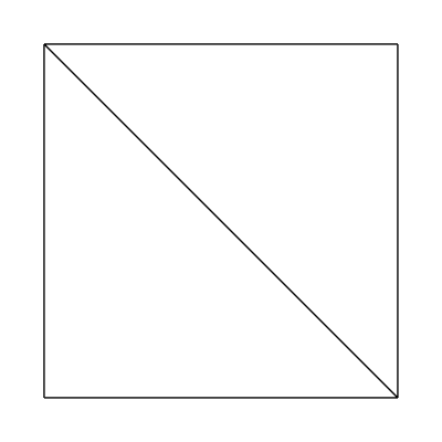
Take a look at the following picture:
![Attached Image: pic1.png]()
As you can see, the exact same vector v can be defined by using different coordinate systems. In each of those systems, this vector will have its own coordinates, relative to the origin of system. How do we get vector coordinates relative to frame B, if we know its coordinates in frame A? Well, we can use transformation matrix, corresponding to coordinate system change:
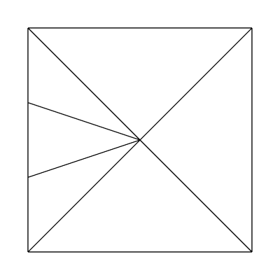
w component of the sequence in square brackets indicates if we want to convert coordinates of the vector or coordinates of the point. If w component is equal to zero - it is a vector, otherwise it is a point. This component is very important, because unlike vectors, points rely on exact position in space, thus, we need to consider coordinate system’s origin transformation as well. It is well illustrated on the following picture:
![Attached Image: pic2.png]()
The view transformation matrix for our illustration looks like this:
![Attached Image: pic2.1.png]()
Note that for vector (it means w component is equal to zero) Q is not needed, since multiplication by zero w component will discard it anyway. The matrix above helps us to change coordinate system from world to camera-relative.
Next, we have to project resulted camera-relative point coordinates onto 2D plane. The result M matrix will be:
Thus, the final equation will be:
Let us discuss how to construct the projection matrix.
There are different types of projection matrices exist. One is called orthogonal matrix and other is called perspective matrix.
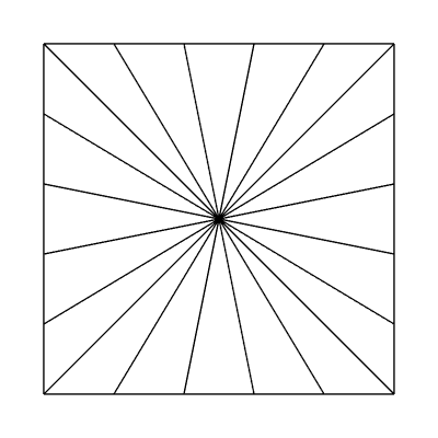
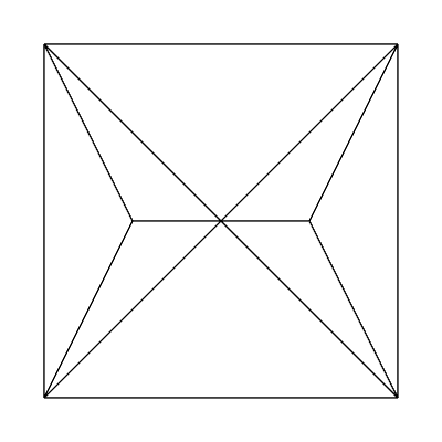
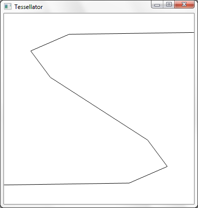
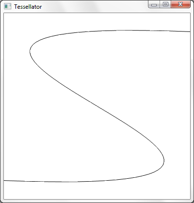
Orthogonal matrix serves for projecting 3D point into 2D without saving 3D illusion. This type of projection is often used for drawing UI sprites or text – those objects usually should not be resized regardless of their distance from camera. The following illustration roughly shows how orthogonal projection looks like:
![Attached Image: pic3.png]()
View frustum is a spatial volume, limited by 4 planes (top, left, bottom and right) and other two planes, called near clip plane and far clip plane. All objects inside this frustum will be projected right onto the screen plane. Near and far clip planes are needed for preventing the rendering of too far or too close objects to the player. None of scene objects beyond far clip plane or closer to the camera than near clip plane will be presented on projection window. This greatly increases performance and avoid the waste of video card resources.
However, as we mentioned before, the picture produced by orthogonal projection is not realistic. Two objects with the same size, but with different distance from the camera will have absolutely the same size on the projection window. So what about realistic perspective projection?
Let us talk about the nature of human vision to understand concepts behind the perspective projection. The human eyes see objects in a distance as if those objects would be smaller than those placed closer to the eye would. In 3D, it is called perspective. Just look through the window and you can see that buildings outside it look smaller than the window itself – this is perspective effect. Artists usually use this effect to create 3D illusion on the paper. This is one of the simple but effective techniques contributing to the scene realism.
Another interesting feature of our vision is that it is limited by view angle – we cannot see everything around us at the same time. So how can we simulate our eyes behavior in game, taking everything we have discussed before into consideration?
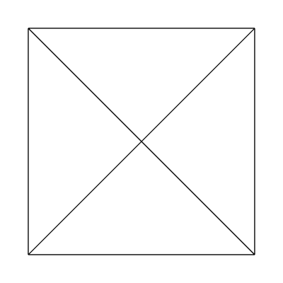
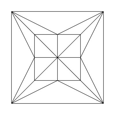
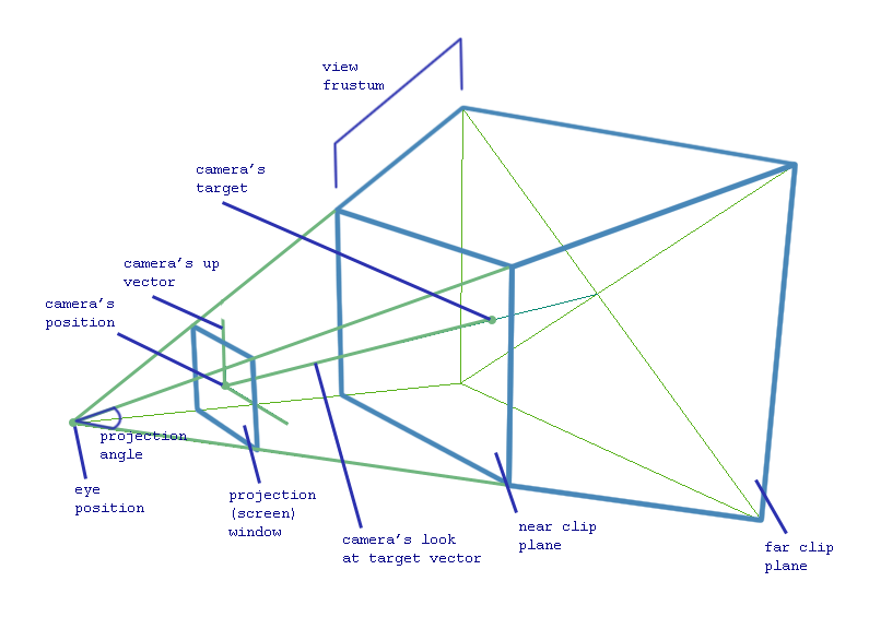
Here comes the concept of perspective view frustum. The view frustum is a space volume, visible by our eyes, which we want to project onto the screen. The screen comes as a rough approximation of human viewing mechanism, which usually composed out of two images, received by two human eyes. Here is illustration of perspective view frustum:
![Attached Image: pic4.png]()
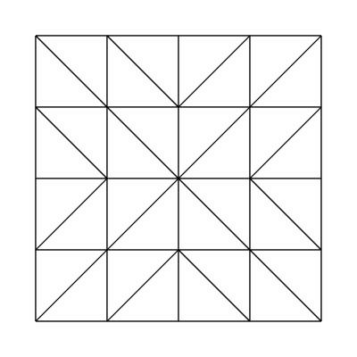
Here is how we project objects onto the screen plane (recall that it is our screen window) depending on their distance from the camera:
![Attached Image: pic5.png]()
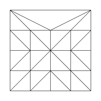
Each 3D point will have a new coordinates (x', y', z', w') after applying transformation matrix M. If you divide x' and y' coordinates by w' you will get normalized device coordinates in range [-1; 1], which is then mapped by shaders and viewport right onto the screen. Remained z' coordinate serves for depth information, which helps to recognize the order in which primitives are drawn into the screen.
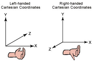
Luckily for us, DirectX has a big number of built-in functions for managing view and projection matrices without extensive complex math involved on our side. DirectX uses left-handed coordinate system:
![Attached Image: pic6.png]()
Thus our most involved functions will be:
XMMatrixLookAtLH(XMVECTOR position, XMVECTOR target, XMVECTOR up_direction)
XMMatrixPerspectiveFovLH(float radians, float ratio, float near_plane, float far_plane)
XMMatrixOrthographicLH(float view_width, float view_height, float near_plane, far_plane)
All of input parameters for those functions can be easily obtained from picture 3, so let us briefly define them:
Why do we need a separate class for our camera anyway? Well, we can directly specify all transformation matrices right in our code. But soon or later we would want to make our look at the scene more dynamic – e.g. change its position according to keyboard or mouse input. So the process of managing matrices recreation will become a nightmare. Here comes our class, which will have a very human-friendly interfaces to control camera movement.
Let us define the functionality of this class first. It will contain camera view matrix, orthogonal and perspective projection matrices and provide interface for accessing those matrices. In addition, there will be a method, which will allow us to resize of our camera's view frustum. This is needed when we want to resize our application window or if we want to render more objects into texture etc. Moreover, our camera will have an ability to change its position, moving along specified axis, changing the target itself and of course rotating the camera around itself.
At instantiation time, we create a camera at (0, 0, -1) point coordinates, target (0, 0, 0) and up vector looking along y-axis. We will store those values in our class along with view and projection matrices and their parameters. Note that we will store the end-point of up-vector, not the vector itself. After camera object instantiation, class-consumer must call InitProjMatrix() or InitOrthoMatrix() methods or both. Those methods will construct initial projection matrices for our camera view frustum, so we can acess them later from camera-class users.
Here is the code for our camera-control class, but don't worry, we will discuss it below:
First of all, let me briefly explain what is DirectXMath, so this code will become more clear for those who don’t know anything about it yet. DirectXMath is a set of wrappers for SSE operations over SIMD-compatible processor registers. They offer parallel processing of operations over matrices and vertices such as multiplication, division and so on. So theoretically, they give us a good speedup, if used right. It means you have to do as many operations as you can over loaded into SIMD-compatible processor registers data while it is still here. Obviously, the code above is not actually utilize this feature. I just used this library and not D3DX one because the latter is deprecated in Windows 8. You can disable this behavior in Visual Studio project settings so you will not get any parallel advantages.
Additionally, DirectXMath has a number of new types. They can be divided into storage data types and SIMD data types. The majority of operations are implemented for SIMD data types – so called worker data types. So, when you want to call them, you have to load data from storage type into SIMD type, process it and store it back. Storage classes are XMFLOAT2, XMFLOAT3, XMFLOAT4, XMINT2 and other similar for vectors, XMFLOAT3X3, XMFLOAT4X4 and similar for matrices. Vectorized data types are XMVECTOR and XMMATRIX – those will be your main workers.
You can read up a lot more about DirectXMath library here.
Therefore, we store camera position, target and up coordinates in XMFLOAT3 type. Matrices are stored within XMFLOAT4X4 data type. For operations over data, we load it into SIMD-types and process it.
Let us look at the code and explain some unclear moments. First of all, we have a constructor which initializes our camera view matrix with previously specified requirements for its default position, target and up coordinates. Constructor calls initViewMatrix() private class method, which is responsible for view matrix production from given inner position, target and up class properties.
Next, we have to construct our projection matrices outside of the class, on demand. InitProjMatrix() and InitOrthoMatrix() public methods are responsible for that. If you call any of those methods, they will store their input parameters inside the class private properties and produce corresponding matrix, which will be stored inside the class as well. As you can see, near plane for orthogonal matrix is always 0.0f – that’s because we don’t have to clip any UI geometry for which this matrix will be used. Also it is highly possible that Z buffer will be turned off when rendering UI, so depth information doesn’t really matter. You can change this behavior, if you are planning to clip some of the objects used in combination with orthogonal matrix in the future.
In order to handle screen resizing we provide OnResize() method, which will simply recreate our projection matrices with new parameters.
Take a special look at matrices accessors. As you can clearly see, they call XMMatrixTranspose before returning property value. That is because XMMATRIX stores its data in row-major order, but shader programs use column-major order. Since shaders are the common consumers for our matrices, we integrate matrix-transpose functionality right into accessor. You can change it, but do not forget about this behavior.
Now it is time to discuss move, rotate and change camera/target position functionality.
The movement is a very simple. Take a look at Move(XMFLOAT3) method. It changes position, target and up-end point coordinates of camera by adding input vector to the current ones. Thus, camera vectors will not change, hence camera will keep looking along the same direction and will not rotate anywhere. This effect can be illustrated if you keep looking ahead while jumping up or strafing left, right; moving back or forward.
Rotation. Rotation is the most interesting among other camera features. Along with camera rotation around specific angle, rotation will allow us to implement the change of camera position or camera’s target position in future without unneeded complexity. We will rotate our camera around axis, provided as function input, which must be in camera-bound 3D space. Also do not forget that angle in left-handed system is measured clockwise when looking from the end of the vector to its origin. This is very important.
The algorithm for camera rotation is following:
So now we can take a look at camera target change function. Basically, we calculate two vectors – old look-at-target vector and new look-at-target vector. Next, we find an angle between those vectors and their cross product:
![Attached Image: pic7.png]()
Since our system is left-handed, a x b(RH) is equal to b x a(LH). This cross-product vector will be an axis for our camera rotation. When we have an angle and axis, we can use Rotate(axis, angle), implemented earlier.
Almost the same algorithm goes for changing camera position, but we can cheat here by using previously implemented target changing method. Move our camera into new position, and then set the camera’s target to the old one.
There are so-called aircraft principal axes – pitch, roll and yaw:
![Attached Image: pic8.png]()
Those are usually used in space-ship battle games, where you have free movements. By means of our camera class, implemented above, we can easily model this behavior:
Here is a complete code of our result:
https://code.google.com/p/camera-class/source/browse/#svn%2Ftrunk
Good luck and make some entertaining games! =)
When you construct your 3D scene (every point in this space has three coordinates – x, y, z), you have to present it on the screen somehow. However, the monitor screen is a flat surface made up of pixels and thus has 2D coordinate system, not 3D. The camera abstraction class contains various transformation matrices inside itself and aims to address this contradiction. Additionally you can use this class when rendering scene from the light point of view to create shadow mapping or specify player’s behavior or to achieve other similar effects. It is extremely useful in rendering.
Basics
Firstly, let us discuss the concept of transformation matrices. We will need them for converting object points’ coordinates into camera-relative coordinates. If you know the basics, feel free to skip this part of the article and move on right to implementation part.
Take a look at the following picture:
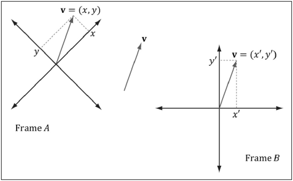
As you can see, the exact same vector v can be defined by using different coordinate systems. In each of those systems, this vector will have its own coordinates, relative to the origin of system. How do we get vector coordinates relative to frame B, if we know its coordinates in frame A? Well, we can use transformation matrix, corresponding to coordinate system change:
[x', y', z', w'] = [x, y, z, w] * View
w component of the sequence in square brackets indicates if we want to convert coordinates of the vector or coordinates of the point. If w component is equal to zero - it is a vector, otherwise it is a point. This component is very important, because unlike vectors, points rely on exact position in space, thus, we need to consider coordinate system’s origin transformation as well. It is well illustrated on the following picture:
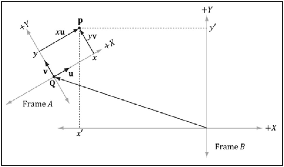
The view transformation matrix for our illustration looks like this:
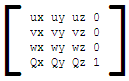
Note that for vector (it means w component is equal to zero) Q is not needed, since multiplication by zero w component will discard it anyway. The matrix above helps us to change coordinate system from world to camera-relative.
Next, we have to project resulted camera-relative point coordinates onto 2D plane. The result M matrix will be:
M = View * Projection
Thus, the final equation will be:
[x', y', z', w'] = [x, y, z, w] * View * Projection
Let us discuss how to construct the projection matrix.
There are different types of projection matrices exist. One is called orthogonal matrix and other is called perspective matrix.
Orthogonal matrix serves for projecting 3D point into 2D without saving 3D illusion. This type of projection is often used for drawing UI sprites or text – those objects usually should not be resized regardless of their distance from camera. The following illustration roughly shows how orthogonal projection looks like:
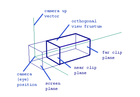
View frustum is a spatial volume, limited by 4 planes (top, left, bottom and right) and other two planes, called near clip plane and far clip plane. All objects inside this frustum will be projected right onto the screen plane. Near and far clip planes are needed for preventing the rendering of too far or too close objects to the player. None of scene objects beyond far clip plane or closer to the camera than near clip plane will be presented on projection window. This greatly increases performance and avoid the waste of video card resources.
However, as we mentioned before, the picture produced by orthogonal projection is not realistic. Two objects with the same size, but with different distance from the camera will have absolutely the same size on the projection window. So what about realistic perspective projection?
Let us talk about the nature of human vision to understand concepts behind the perspective projection. The human eyes see objects in a distance as if those objects would be smaller than those placed closer to the eye would. In 3D, it is called perspective. Just look through the window and you can see that buildings outside it look smaller than the window itself – this is perspective effect. Artists usually use this effect to create 3D illusion on the paper. This is one of the simple but effective techniques contributing to the scene realism.
Another interesting feature of our vision is that it is limited by view angle – we cannot see everything around us at the same time. So how can we simulate our eyes behavior in game, taking everything we have discussed before into consideration?
Here comes the concept of perspective view frustum. The view frustum is a space volume, visible by our eyes, which we want to project onto the screen. The screen comes as a rough approximation of human viewing mechanism, which usually composed out of two images, received by two human eyes. Here is illustration of perspective view frustum:
Here is how we project objects onto the screen plane (recall that it is our screen window) depending on their distance from the camera:
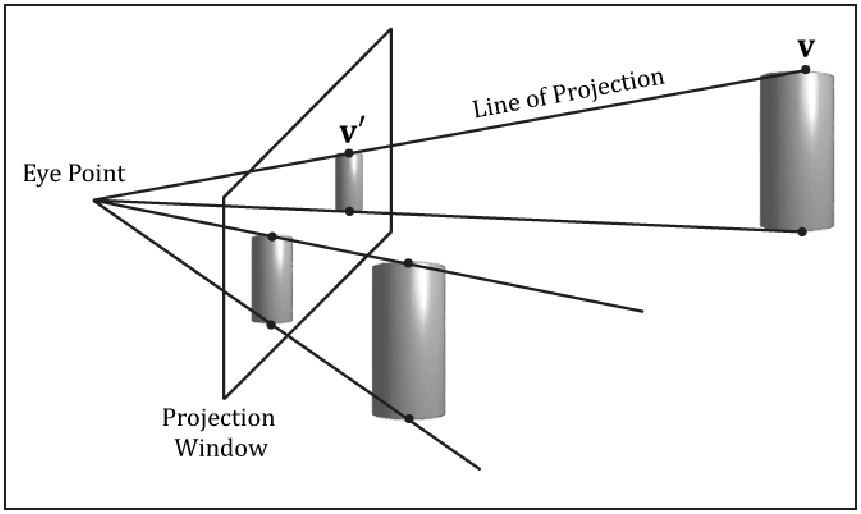
Each 3D point will have a new coordinates (x', y', z', w') after applying transformation matrix M. If you divide x' and y' coordinates by w' you will get normalized device coordinates in range [-1; 1], which is then mapped by shaders and viewport right onto the screen. Remained z' coordinate serves for depth information, which helps to recognize the order in which primitives are drawn into the screen.
Implementation
Luckily for us, DirectX has a big number of built-in functions for managing view and projection matrices without extensive complex math involved on our side. DirectX uses left-handed coordinate system:
Thus our most involved functions will be:
XMMatrixLookAtLH(XMVECTOR position, XMVECTOR target, XMVECTOR up_direction)
XMMatrixPerspectiveFovLH(float radians, float ratio, float near_plane, float far_plane)
XMMatrixOrthographicLH(float view_width, float view_height, float near_plane, far_plane)
All of input parameters for those functions can be easily obtained from picture 3, so let us briefly define them:
- position – camera position coordinates in world coordinate system;
- target – camera’s focus target position. Note that this point must lie on the line of look at target vector in picture 3;
- up_direction – camera coordinate system up vector. Usually this is (0, 1, 0), but if we want our camera to be free, we have to track this vector changes by our own;
- radians – the angle between view frustum’s upper plane and bottom plane in radians, projection angle;
- ratio – this is a result of division between projection’s width and height. Usually this is the same as screen_width/screen_height;
- near_plane, far_plane – those parameters define the distance of corresponding clip planes from camera position measured along look-at-target axis;
- view_width, view_height – the width and height of orthogonal frustum.
Why do we need a separate class for our camera anyway? Well, we can directly specify all transformation matrices right in our code. But soon or later we would want to make our look at the scene more dynamic – e.g. change its position according to keyboard or mouse input. So the process of managing matrices recreation will become a nightmare. Here comes our class, which will have a very human-friendly interfaces to control camera movement.
Let us define the functionality of this class first. It will contain camera view matrix, orthogonal and perspective projection matrices and provide interface for accessing those matrices. In addition, there will be a method, which will allow us to resize of our camera's view frustum. This is needed when we want to resize our application window or if we want to render more objects into texture etc. Moreover, our camera will have an ability to change its position, moving along specified axis, changing the target itself and of course rotating the camera around itself.
At instantiation time, we create a camera at (0, 0, -1) point coordinates, target (0, 0, 0) and up vector looking along y-axis. We will store those values in our class along with view and projection matrices and their parameters. Note that we will store the end-point of up-vector, not the vector itself. After camera object instantiation, class-consumer must call InitProjMatrix() or InitOrthoMatrix() methods or both. Those methods will construct initial projection matrices for our camera view frustum, so we can acess them later from camera-class users.
Here is the code for our camera-control class, but don't worry, we will discuss it below:
//GCamera.h
#pragma once
#include "GUtility.h"

namespace Game
{
////////////////////////////////////////////////////////
// Stores View and Projection matrices used by shaders
// to translate 3D world into 2D screen surface
// Camera can be moved and rotated. Also, user can change
// camera's target and position
////////////////////////////////////////////////////////
class GCamera
{
public:
	// Constructs default camera looking at 0,0,0
	// placed at 0,0,-1 with up vector 0,1,0 (note that mUp is NOT a vector - it's vector's end)
    GCamera(void);
	// Create camera, based on another one
	GCamera(const GCamera& camera);
	// Copy all camera's parameters
    GCamera& operator=(const GCamera& camera);
    ~GCamera(void) {}

private:
	// Initialize camera's View matrix from mPosition, mTarget and mUp coordinates
	void initViewMatrix();

public:
	// Initialize camera's perspective Projection matrix
	void InitProjMatrix(const float angle, const float client_width, const float client_height,
		const float nearest, const float farthest);
	// Initialize camera's orthogonal projection
	void InitOrthoMatrix(const float client_width, const float client_height,
		const float near_plane, const float far_plane);

	// Resize matrices when window size changes
	void OnResize(uint32_t new_width, uint32_t new_height);

	///////////////////////////////////////////////
	/*** View matrix transformation interfaces ***/
	///////////////////////////////////////////////

	// Move camera
	void Move(XMFLOAT3 direction);
	// Rotate camera around `axis` by `degrees`. Camera's position is a
	// pivot point of rotation, so it doesn't change
	void Rotate(XMFLOAT3 axis, float degrees);
	// Set camera position coordinates
    void Position(XMFLOAT3& new_position);
	// Get camera position coordinates
	const XMFLOAT3& Position() const { return mPosition; }
	// Change camera target position
	void Target(XMFLOAT3 new_target);
	// Get camera's target position coordinates
	const XMFLOAT3& Target() const { return mTarget; }
	// Get camera's up vector
	const XMFLOAT3 Up() { return GMathVF(GMathFV(mUp) - GMathFV(mPosition)); }
	// Get camera's look at target vector
	const XMFLOAT3 LookAtTarget() { return GMathVF(GMathFV(mTarget) - GMathFV(mPosition)); }
	// Returns transposed camera's View matrix
    const XMFLOAT4X4 View() { return GMathMF(XMMatrixTranspose(GMathFM(mView))); }

	/////////////////////////////////////////////////////
	/*** Projection matrix transformation interfaces ***/
	/////////////////////////////////////////////////////

	// Set view frustum's angle
	void Angle(float angle);
	// Get view frustum's angle
	const float& Angle() const { return mAngle; }

	// Set nearest culling plane distance from view frustum's projection plane
	void NearestPlane(float nearest);
	// Set farthest culling plane distance from view frustum's projection plane
	void FarthestPlane(float farthest);

	// Returns transposed camera's Projection matrix
	const XMFLOAT4X4 Proj() { return GMathMF(XMMatrixTranspose(GMathFM(mProj))); }
	// Returns transposed orthogonal camera matrix
	const XMFLOAT4X4 Ortho() { return GMathMF(XMMatrixTranspose(GMathFM(mOrtho))); }

private:
    /*** Camera parameters ***/
    XMFLOAT3 mPosition;		// Camera's coordinates
    XMFLOAT3 mTarget;		// View target's coordinates
    XMFLOAT3 mUp;			// Camera's up vector end coordinates

	/*** Projection parameters ***/
	float mAngle;			// Angle of view frustum
	float mClientWidth;		// Window's width
	float mClientHeight;	// Window's height
	float mNearest;			// Nearest view frustum plane
	float mFarthest;		// Farthest view frustum plane

    XMFLOAT4X4  mView;		// View matrix
	XMFLOAT4X4	mProj;		// Projection matrix
	XMFLOAT4X4	mOrtho;		// Ortho matrix for drawing without tranformation
};

} // namespace Game
//GCamera.cpp
#include "GCamera.h"

namespace Game
{

GCamera::GCamera(void)
{
    mPosition		= XMFLOAT3(0.0f, 0.0f, -1.0f);
    mTarget			= XMFLOAT3(0.0f, 0.0f, 0.0f);
    mUp				= GMathVF(GMathFV(mPosition) + GMathFV(XMFLOAT3(0, 1, 0)));
	this->initViewMatrix();

	mAngle			= 0.0f;
	mClientWidth	= 0.0f;
	mClientHeight	= 0.0f;
	mNearest		= 0.0f;
	mFarthest		= 0.0f;

	XMStoreFloat4x4(&mView, XMMatrixIdentity());
	XMStoreFloat4x4(&mProj, XMMatrixIdentity());
	XMStoreFloat4x4(&mOrtho, XMMatrixIdentity());
}

GCamera::GCamera(const GCamera& camera)
{
	*this = camera;
}

GCamera& GCamera::operator=(const GCamera& camera)
{
    mPosition		= camera.mPosition;
    mTarget			= camera.mTarget;
    mUp				= camera.mUp;

	mAngle			= camera.mAngle;
	mClientWidth	= camera.mClientWidth;
	mClientHeight	= camera.mClientHeight;
	mNearest		= camera.mNearest;
	mFarthest		= camera.mFarthest;

    mView			= camera.mView;
	mProj			= camera.mProj;
	mOrtho			= camera.mOrtho;
    return *this;
}

void GCamera::initViewMatrix()
{
	XMStoreFloat4x4(&mView, XMMatrixLookAtLH(XMLoadFloat3(&mPosition), XMLoadFloat3(&mTarget),
		XMLoadFloat3(&this->Up())));
}

void GCamera::InitProjMatrix(const float angle, const float client_width, const float client_height,
								const float near_plane, const float far_plane)
{
	mAngle = angle;
	mClientWidth = client_width;
	mClientHeight = client_height;
	mNearest = near_plane;
	mFarthest = far_plane;
	XMStoreFloat4x4(&mProj, XMMatrixPerspectiveFovLH(angle, client_width/client_height,
		near_plane, far_plane));
}

void GCamera::Move(XMFLOAT3 direction)
{
	mPosition = GMathVF(XMVector3Transform(GMathFV(mPosition),
		XMMatrixTranslation(direction.x, direction.y, direction.z)));
	mTarget = GMathVF(XMVector3Transform(GMathFV(mTarget),
		XMMatrixTranslation(direction.x, direction.y, direction.z)));
	mUp = GMathVF(XMVector3Transform(GMathFV(mUp),
		XMMatrixTranslation(direction.x, direction.y, direction.z)));

	this->initViewMatrix();
}

void GCamera::Rotate(XMFLOAT3 axis, float degrees)
{
	if (XMVector3Equal(GMathFV(axis), XMVectorZero()) ||
		degrees == 0.0f)
		return;

	// rotate vectors
	XMFLOAT3 look_at_target = GMathVF(GMathFV(mTarget) - GMathFV(mPosition));
	XMFLOAT3 look_at_up = GMathVF(GMathFV(mUp) - GMathFV(mPosition));
	look_at_target = GMathVF(XMVector3Transform(GMathFV(look_at_target),
		XMMatrixRotationAxis(GMathFV(axis), XMConvertToRadians(degrees))));
	look_at_up = GMathVF(XMVector3Transform(GMathFV(look_at_up),
		XMMatrixRotationAxis(GMathFV(axis), XMConvertToRadians(degrees))));

	// restore vectors's end points mTarget and mUp from new rotated vectors
	mTarget = GMathVF(GMathFV(mPosition) + GMathFV(look_at_target));
	mUp = GMathVF(GMathFV(mPosition) + GMathFV(look_at_up));

	this->initViewMatrix();
}

void GCamera::Target(XMFLOAT3 new_target)
{
	if (XMVector3Equal(GMathFV(new_target), GMathFV(mPosition)) ||
		XMVector3Equal(GMathFV(new_target), GMathFV(mTarget)))
		return;

	XMFLOAT3 old_look_at_target = GMathVF(GMathFV(mTarget) - GMathFV(mPosition));
	XMFLOAT3 new_look_at_target = GMathVF(GMathFV(new_target) - GMathFV(mPosition));
	float angle = XMConvertToDegrees(XMVectorGetX(
		XMVector3AngleBetweenNormals(XMVector3Normalize(GMathFV(old_look_at_target)),
		XMVector3Normalize(GMathFV(new_look_at_target)))));
	if (angle != 0.0f && angle != 360.0f && angle != 180.0f)
	{
		XMVECTOR axis = XMVector3Cross(GMathFV(old_look_at_target), GMathFV(new_look_at_target));
		Rotate(GMathVF(axis), angle);
	}
	mTarget = new_target;
	this->initViewMatrix();
}

// Set camera position
void GCamera::Position(XMFLOAT3& new_position)
{
	XMFLOAT3 move_vector = GMathVF(GMathFV(new_position) - GMathFV(mPosition));
	XMFLOAT3 target = mTarget;
	this->Move(move_vector);
	this->Target(target);
}

void GCamera::Angle(float angle)
{
	mAngle = angle;
	InitProjMatrix(mAngle, mClientWidth, mClientHeight, mNearest, mFarthest);
}

void GCamera::NearestPlane(float nearest)
{
	mNearest = nearest;
	OnResize(mClientWidth, mClientHeight);
}

void GCamera::FarthestPlane(float farthest)
{
	mFarthest = farthest;
	OnResize(mClientWidth, mClientHeight);
}

void GCamera::InitOrthoMatrix(const float clientWidth, const float clientHeight,
		const float nearZ, const float fartherZ)
{
	XMStoreFloat4x4(&mOrtho, XMMatrixOrthographicLH(clientWidth, clientHeight, 0.0f, fartherZ));
}

void GCamera::OnResize(uint32_t new_width, uint32_t new_height)
{
	mClientWidth = new_width;
	mClientHeight = new_height;
	InitProjMatrix(mAngle, static_cast<float>(new_width), static_cast<float>(new_height), mNearest, mFarthest);
	InitOrthoMatrix(static_cast<float>(new_width), static_cast<float>(new_height), 0.0f, mFarthest);
}

}
// GUtility.h
#pragma once
#include <windows.h>

#include <d3d11.h>
#include <directxmath.h>
#include <iostream>

using namespace DirectX;

inline XMVECTOR GMathFV(XMFLOAT3& val)
{
	return XMLoadFloat3(&val);
}

inline XMFLOAT3 GMathVF(XMVECTOR& vec)
{
	XMFLOAT3 val;
	XMStoreFloat3(&val, vec);
	return val;
}
First of all, let me briefly explain what is DirectXMath, so this code will become more clear for those who don’t know anything about it yet. DirectXMath is a set of wrappers for SSE operations over SIMD-compatible processor registers. They offer parallel processing of operations over matrices and vertices such as multiplication, division and so on. So theoretically, they give us a good speedup, if used right. It means you have to do as many operations as you can over loaded into SIMD-compatible processor registers data while it is still here. Obviously, the code above is not actually utilize this feature. I just used this library and not D3DX one because the latter is deprecated in Windows 8. You can disable this behavior in Visual Studio project settings so you will not get any parallel advantages.
Additionally, DirectXMath has a number of new types. They can be divided into storage data types and SIMD data types. The majority of operations are implemented for SIMD data types – so called worker data types. So, when you want to call them, you have to load data from storage type into SIMD type, process it and store it back. Storage classes are XMFLOAT2, XMFLOAT3, XMFLOAT4, XMINT2 and other similar for vectors, XMFLOAT3X3, XMFLOAT4X4 and similar for matrices. Vectorized data types are XMVECTOR and XMMATRIX – those will be your main workers.
You can read up a lot more about DirectXMath library here.
Therefore, we store camera position, target and up coordinates in XMFLOAT3 type. Matrices are stored within XMFLOAT4X4 data type. For operations over data, we load it into SIMD-types and process it.
Let us look at the code and explain some unclear moments. First of all, we have a constructor which initializes our camera view matrix with previously specified requirements for its default position, target and up coordinates. Constructor calls initViewMatrix() private class method, which is responsible for view matrix production from given inner position, target and up class properties.
Next, we have to construct our projection matrices outside of the class, on demand. InitProjMatrix() and InitOrthoMatrix() public methods are responsible for that. If you call any of those methods, they will store their input parameters inside the class private properties and produce corresponding matrix, which will be stored inside the class as well. As you can see, near plane for orthogonal matrix is always 0.0f – that’s because we don’t have to clip any UI geometry for which this matrix will be used. Also it is highly possible that Z buffer will be turned off when rendering UI, so depth information doesn’t really matter. You can change this behavior, if you are planning to clip some of the objects used in combination with orthogonal matrix in the future.
In order to handle screen resizing we provide OnResize() method, which will simply recreate our projection matrices with new parameters.
Take a special look at matrices accessors. As you can clearly see, they call XMMatrixTranspose before returning property value. That is because XMMATRIX stores its data in row-major order, but shader programs use column-major order. Since shaders are the common consumers for our matrices, we integrate matrix-transpose functionality right into accessor. You can change it, but do not forget about this behavior.
Now it is time to discuss move, rotate and change camera/target position functionality.
The movement is a very simple. Take a look at Move(XMFLOAT3) method. It changes position, target and up-end point coordinates of camera by adding input vector to the current ones. Thus, camera vectors will not change, hence camera will keep looking along the same direction and will not rotate anywhere. This effect can be illustrated if you keep looking ahead while jumping up or strafing left, right; moving back or forward.
Rotation. Rotation is the most interesting among other camera features. Along with camera rotation around specific angle, rotation will allow us to implement the change of camera position or camera’s target position in future without unneeded complexity. We will rotate our camera around axis, provided as function input, which must be in camera-bound 3D space. Also do not forget that angle in left-handed system is measured clockwise when looking from the end of the vector to its origin. This is very important.
The algorithm for camera rotation is following:
- We calculate two vectors – look-at-target vector and up vector.
- Construct the rotation matrix from passed into function axis and angle by calling XMMatrixRotationAxis(axis, angle).
- Modify both vectors by this matrix by calling XMMatrixTransform(vector, transform_matrix).
- Restore the coordinates of target and up end points and recreate camera view matrix. Camera position does not change in rotation.
So now we can take a look at camera target change function. Basically, we calculate two vectors – old look-at-target vector and new look-at-target vector. Next, we find an angle between those vectors and their cross product:
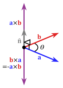
Since our system is left-handed, a x b(RH) is equal to b x a(LH). This cross-product vector will be an axis for our camera rotation. When we have an angle and axis, we can use Rotate(axis, angle), implemented earlier.
Almost the same algorithm goes for changing camera position, but we can cheat here by using previously implemented target changing method. Move our camera into new position, and then set the camera’s target to the old one.
There are so-called aircraft principal axes – pitch, roll and yaw:
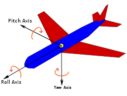
Those are usually used in space-ship battle games, where you have free movements. By means of our camera class, implemented above, we can easily model this behavior:
GCamera camera;
// camera initialization
camera.Rotate(XMFLOAT3(0.0f, 0.0f, 1.0f), 90.0f); // roll by 90 degrees clockwise
// ...
camera.Rotate(XMFLOAT3(1.0f, 0.0f, 0.0f), 90.0f); // pitch by 90 degrees clockwise
// ...
camera.Rotate(XMFLOAT3(0.0f, -1.0f, 0.0f), 90.0f); // yaw by 90 degrees clockwise
Here is a complete code of our result:
https://code.google.com/p/camera-class/source/browse/#svn%2Ftrunk
Good luck and make some entertaining games! =)